Morning
May you help me?
I´m new in forum and first time with I use this equipement.
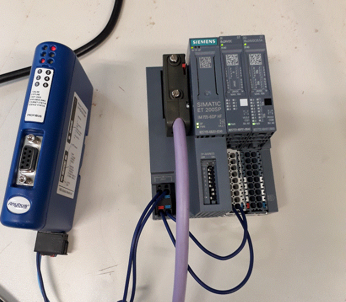
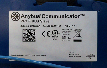
I have an AB7000-C gateway from Anybys, which has already been configured by the equipment supplier, to connect a volume meter to our Siemens plc.
 100%75%50%
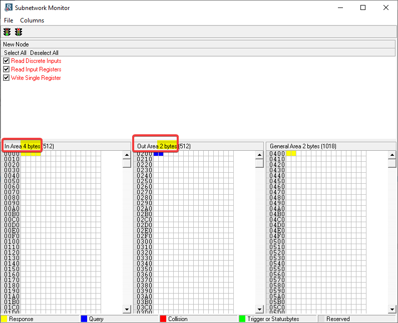
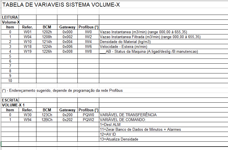
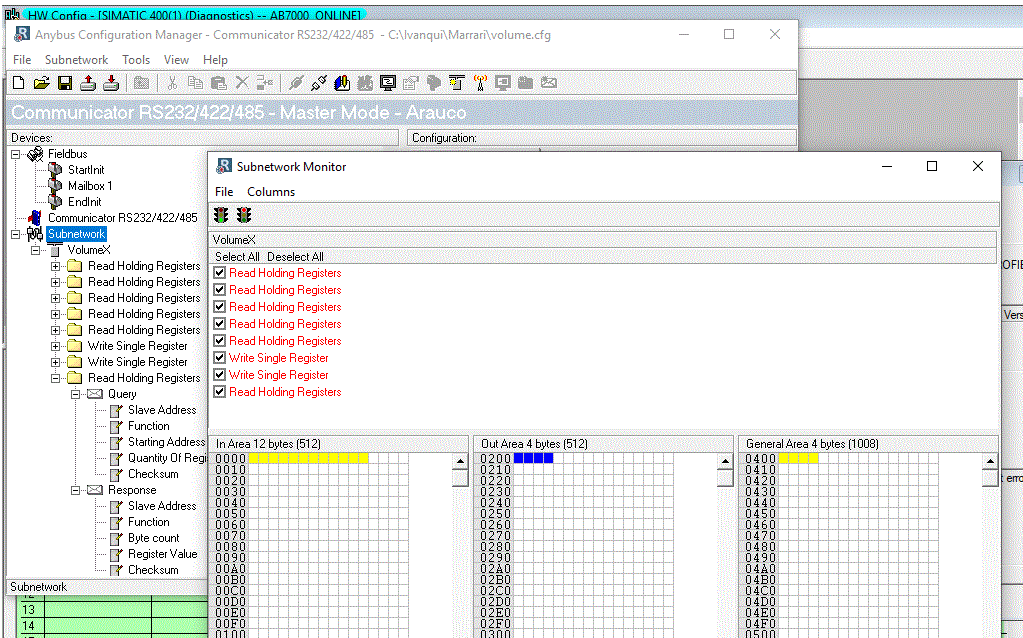
The image below shows the configuration already made by the supplier
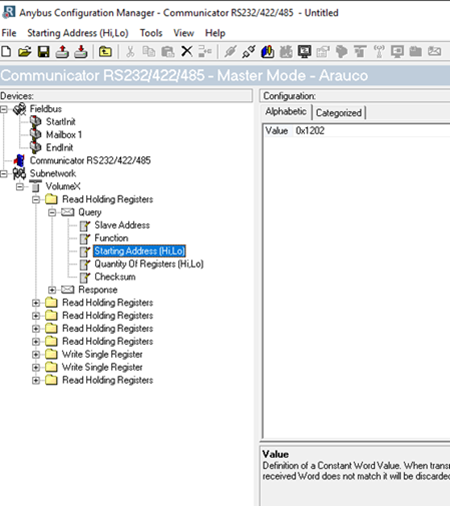
As I understand it we have 5 words for reading, 2 for writing, and 1 more for reading. I don’t know if my interpretation is correct.
To PLC – Siemens
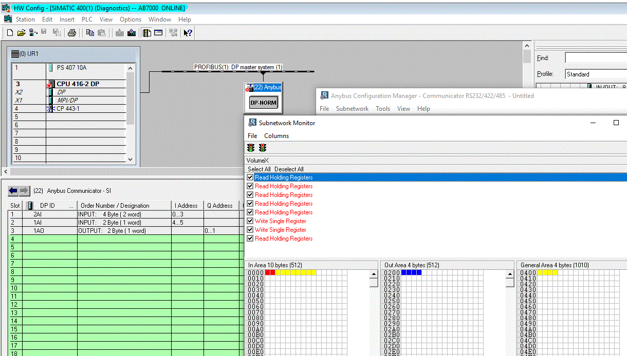
I’m working with Simatic Manager v5.6, which in the hardware catalog already has the Anybus Communicator Slave hardware, but I also installed HMSB1803.gsd, downloaded from the website: https://www.anybus.com/support/file-doc-downloads/communicator-specific/?ordercode=AB7000
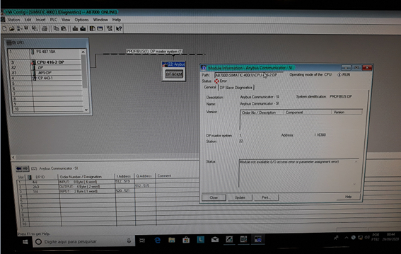
I created a new project on a benchtop plc with a 416-2dp cpu, and inserted the Anybus hardware into the profibus network, used the address 22. The Anybus address was set to 22.
Input words entered
– INPUT – 8byte (4 word),
- OUTPUT – 4 byte (2 word)
- INPUT – 2 bytes (1 word).
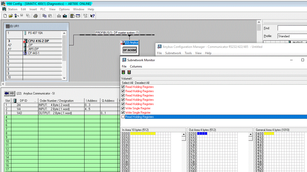
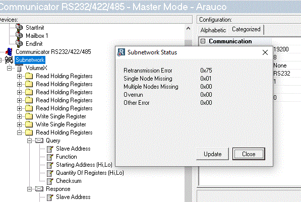
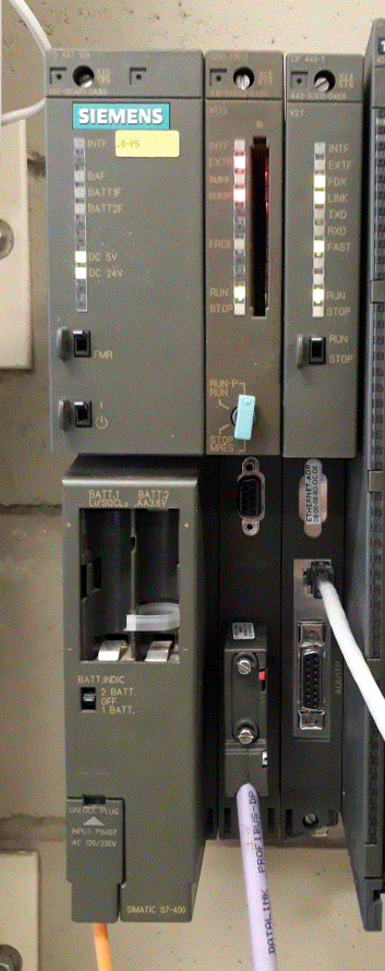
After downloading according to the configurations made above, the gateway fails in the profibus network by the plc hardware, and fails in the BUS2F network, flashes red and the system led is lit red continuously, on the front of the CPU.
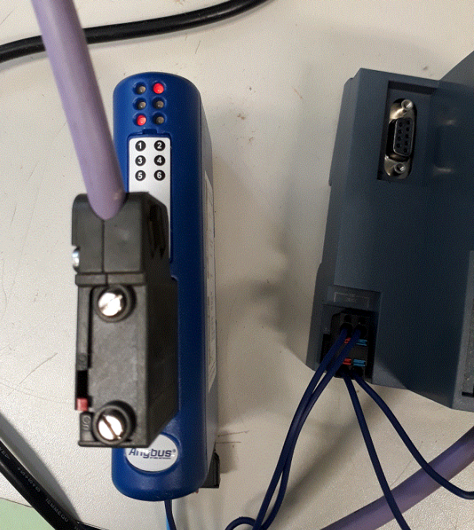
The LEDs on the communicators are as follows:
1 - OFF, 2 - RED, 3 - OFF, 4 - OFF, 5 - RED, 6 - GREEN flashing
The existing fault in the plc hardware is: Module not avaliable (I/O access erro ror parameter assignment error).
 100%75%50%
Tanks!
BR.
Jefferson