AB7000C - How can the subnetwork device prompt a subnetwork produce tranaction?

Background: I’m using the generic data model because my subnetwork device needs to be the one to initiate a consume (by Anybus) transaction. A consume transaction contains the results of a measurement my device takes. (Measurement here is not a continuous thing like temperature from a sensor, but a process that starts and ends after several seconds, does a calculation, then sends result data to the PLC via Anybus. The next measurement is started, etc.)

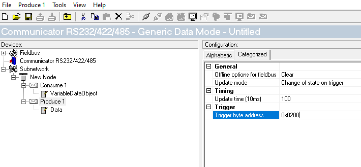
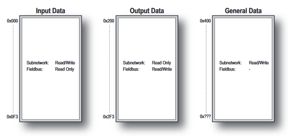
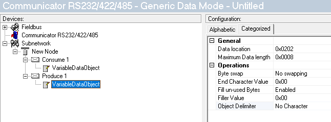
In response to receiving the measurement data, the PLC will change data at an address in Anybus, whose change of state prompts a subnetwork produce transaction (the PLC’s ACK reply). Fine

But my question is, how can my subnetwork device, whenever it wants, prompt the same (subnetwork) produce transaction to be able to read the value of that register the PLC writes to?

That is, if I have doubts that I missed the initial subnetwork produce transaction prompted by the (one shot) change-of-state, How can the subnetwork prompt a re-check of the value of that output memory register?

If you want to prompt a device on the subnet to produce a value on demand, you would configure a trigger byte that you can write to in the PLC, that would send the necessary command to your device on the subnet. It would be a Produce command and look something like this:

Thanks for quick reply.

So, my subnet device needs to send (Anybus consume) a transaction to request that the PLC causes a change of state to the trigger register which in turn prompts a produce transaction back to the subnet device having the desired data? I take it that any data in the Anybus Output memory is not directly (read-only) accessible by the subnet device. That is, it sounds like it cannot be done without involving communication to the PLC, which is no problem – just need to add a bit more programming to the PLC to respond to the subnet’s request. I was just hoping that there was a way that the subnet can (on its own) read anything from either the Input or Output memory…

Please take a look at 2.2 Data Exchange Model in the User Manual. This graphic illustrates that the sub-network device can only read to Output Area, but can read and write to the Input Area:

image

I’m not sure I exactly understand what you mean here:

You are saying, basically, the subnet device needs to request the PLC to request the subnet device to produce the data? If this is the case, the subnet device can write to a byte (AB input data) which the PLC can monitor and then the PLC can write to the Trigge Byte (AB output data) for a Produce transaction (like the one in the screenshot above). You will enter the necessary Data the needs to be sent to the subnet device under the Produce transaction. If it is a known value, you can use a constant, like Byte Constant. If the data will change and you want it to be specified by the PLC, use ‘Data’ for a fixed size or ‘Variable Data’ for a variable size:

image

Ok, so it sounds like I need to send a command to Anybus that triggers a Produce transaction as a reply that contains from the Output Data what I want (size and address offset). I see how to construct the produce transaction that will be the reply, but don’t know how to construct the command string that will be sent from the subnetwork device to tell Anybus to reply using my produce transaction. Can you point me to the section in the Anybus documention that shows how to construct the serial command string to do this? .

You are not going to construct a command string to send to the Anybus. The Anybus is just exchanging data between the subnet and fieldbus networks. You are going to need to exchange data with the Input memory space on the Anybus that the PLC will read and then write to the trigger byte.

I can’t really explain it in any more detail than that because I have no idea what your subnetwork device is or how it works. For example, is it Modbus or a proprietary protocol using ASCII?

In generic terms, there could be a certain bit in it’s memory that it flips when it wants to alert the PLC to ask for the produce. The Anybus will continuously read that bit (technically the whole byte) and map it to a tag in the PLC so when it changes, the PLC can write to the trigger.

Ok, so the Output Data area is only indirectly readable by the subnetwork device, but involves notifying the PLC that I want data out of the Output Data.
(Btw. my device serial communication is just generic ASCII, no protocol type like MODBUS).
This prompts another question: To direct the subnetwork serial data to a particular consume transaction, do I just need to add a unique constant value to act as an transaction ID. For example, I currently only have 1 consume transaction that updates Input Data starting at 0x10: STX+Data String (96 bytes).
So, if I am to add another consume transactions, I’ll need to configure something like this to direct the incoming subnetwork packet to the proper Input Data location:
transaction 1: STX+0x01+data (96 bytes)
transaction 2: STX+0x02+data (1 byte to trigger reply from PLC)

That’s a good point and I suppose you could do it that way, using a transaction ID, but in this case I usually recommend using the Master mode and creating Query/Response transactions.

The reason why I choose Generic Data Model over Master model requires a little more explanation: My device is used to measure imbalance (vibration) in a rotating part. The measurement reports the imbalance amount and phase angle (I.e. where the heavy or light side is so the imbalance can be corrected by removing or adding mass, respectively.). The issue is that its A/D hardware designer did not have the hardware itself buffer the sampled data to some storage memory for later processing by the measurement software. The software itself, during measurement, is in a tight loop polling the hardware to see if an A/D conversion just completed, and if so, put the new value into the memory buffer. Since this process is so time critical, the hardware interrupts are disabled during measurement so the none of the A/D conversions are missed – they construct the imbalance signal (basically a sinewave) and a missed data point will cause a distortion of the sampled signal and result in inaccurate amount/phase angle.
Since the interrupts are disabled, there is no serial port servicing, among other things (USB, networking, etc.). So, any cyclic type communication is out of the question. The measurement device must be the one to initiate communication when it is in the ‘measurement idle’ state.
(If I had my way, I’d do a re-design of the hardware so it at least buffers the A/D data, if not also do the signal processing to just provide an imbalance amount/angle vector quantity that the measurement software can read at it’s relative leisure (once per part rotation – 200Hz at the most.)

Well, that helps me understand the situation. It will still work in master mode, the only difference will be that the Querys and Responses will be associated with each other, where in Generic it is much harder to match them up.

I have basically the same question which I’m not sure was answered. I want the subnetwork device to simply read a byte in the output area without the fieldbus device being involved. According to the Data Exchange Model the subnetwork device is able to read the output memory. How is this accomplished?

That depends on the device. A Modbus device, for example, would use the “Read Holding Registers” command. However, the Fieldbus device has to be involved, because it needs to write the data to the Output area or there will be nothing to read.

I’m using the generic data mode. I know the AB can be set to cyclically transmit the data which I can poll for. I was just wondering if I can read output bytes at will.

You need to create a Produce transaction to send data to the serial device in Generic data mode.