
No it’s not mandatory. Try switching the RS485+ and RS485-.
Yes, in the log. Click the “Start Logging” icon and then let it run for a few seconds and stop it.
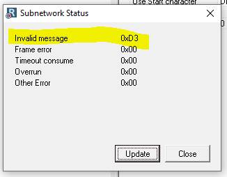
I did it. However I’m start to have errors in the communication between the gateway and the sensor ( I have invalid message error and other error in the Subnetwork status).
In the other way I don’t have errors.

![]()
It seems I’m not receiving anything.
It could be something in the configuration of the gateway or I need to check the configuration of the sensor?
Regards,

![]()
Can you try using a Modbus master simulator, like this one to send commands to sensor and see if y ou get a response?
Thank you so much Kyle. I will try with the Modbus simulator to send the commands to the sensor.
Best regards,
![]()
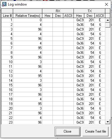
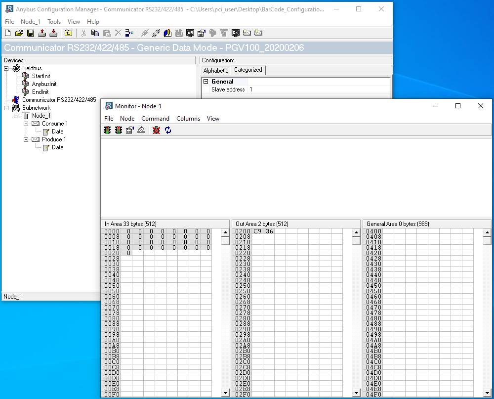
If I chose Update mode = cyclically I can see values transmited on the log windows, but I have invalid message in the subnetwork status :
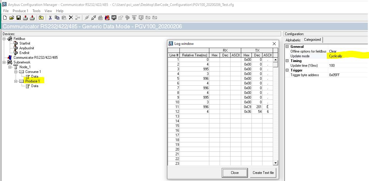
If I configure the Update mode (Producer) to On data change, The invalid message stay at 0 but there is not data transmitted……

![]()
On data change is only going to transmit when the data changes, so if you are using constants, it’s never going to.
You can also use a trigger byte, which you can write from the PLC.
Have you tested the command with a Modbus simulator?
If change the data manually with the update mode set as on data change, I can see values on the log windows but the invalid message increase by 1

![]()
Kyle, I’m changing the data and now I’m seeing values transmitted in the log window. However, I’m still having the invalid message error.
Modbus Simulator. Right now I have the PLC connected to the Anybus and also the sensor connected to the Anybus as well my laptop. How do I have to connect
my laptop to the network? My laptop hast o be the master instead the PLC? Sorry the question but I’m a little confused.

![]()
We were talking about using the Modbus Simulator for testing the sensor. You would just connect the sensor to your laptop, most likely with a USB to serial adapter.
But if you are getting a response, please share the logs.
Hi Kyle,
I couldn’t connect with the sensor using the Modbus scanner. However, I used:
Pepperl & Fuchs Vision configurator software
Serial port monitor software
Serial to USB converter
Using the vision configurator, I configured the sensor as follow:
Baud Rate: 57600
Slave: 1
Data bits: 8
Parity: Even
Stop Bit: 1


![]()
test.xlsx (68.3 KB)
I don’t understand why that works, but the Modbus scanner does not. We may have to do a Teamviewer session to get to the bottom of this. If we can’t get it working, we’ll have to contact the OEM.
Hi Kyle, I received this answer from the Pepperl Fuchs Expert. I have configured and connected the sensor as RS485 ( pins 8 and 9) however they are using RS232. What do
you think?
![]()
If the sensor is the only device connected to the AB7010 than you can use RS232. If you have the Anybus configured to RS485 and the sensor to RS232, that would explain why you are not getting a response. Make sure they both match.
Hello Matias,
a colleague of mine die some testes using Docklight. He did not find any problems with the commands so if you are getting no response back then there has to be a communication issue such as incorrect baud rate, port number, etc.
He is getting back a response that “Lane selection” has not been set but you should always get some response back if it is communicating.
Best regards,
Lucy Wright
Field Application Engineer, Factory Automation Systems
Hello Lucy,
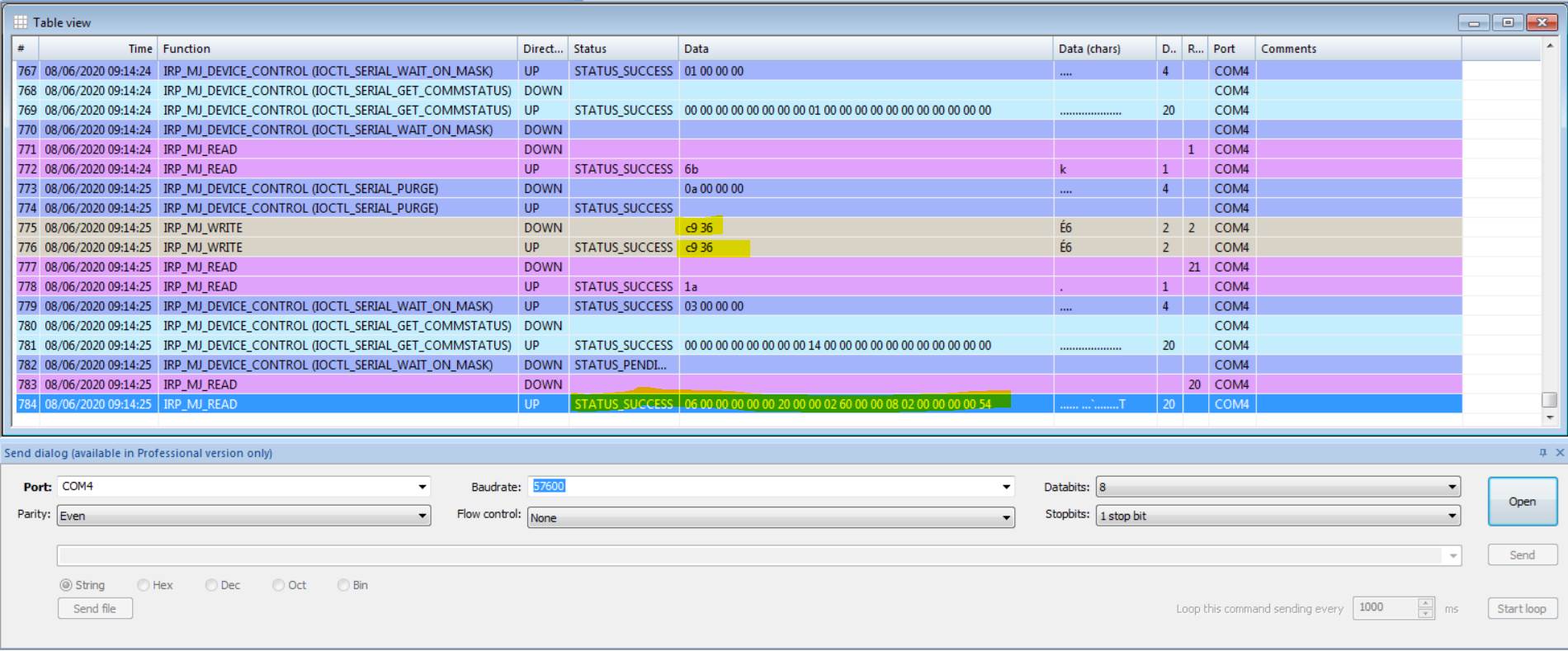
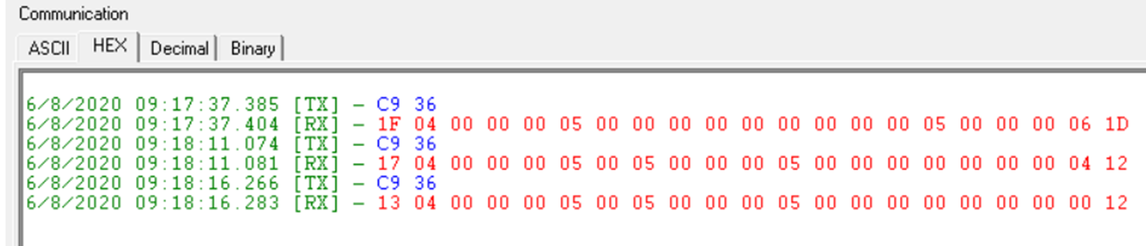
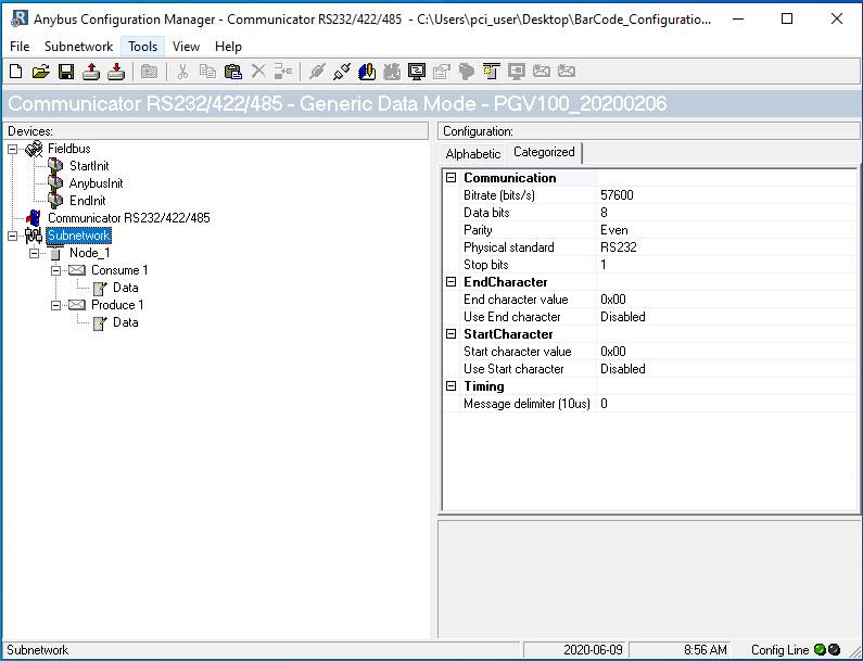
I know the default bd rate is 115200, however the maximum bd rate of my gateway is 57600. So I’m doing the test with that speed. Using your software I can read the values from the sensor ( 57600, 8,E,1 and slave #1
Please, could you confirm that the command (0xC9 0x36)that I’m sending to the sensor is correct. Because when I sent the command from the PLC I don’t have any answer from the sensor.
Best regards.
Matias Lasarte
Programmer - Designer
Hello Matias,
what is the Bd rate set up? Is the Bd rate the same?
The default is 115,200 not 57,600.
Best regards,
Lucy Wright
Field Application Engineer, Factory Automation Systems
Hello Lucy,
- I’m using a different 5VDC.
- Setup serial interface 57600 bps, Even Parity, 8 data bits, 1 stop bit
- The PGV is at Address 1, so I’m sending the follow two bytes as command: 0xC9 0x36
- I configured the sensor using the soft. Connected to the soft the sensor works perfectly.
- I’m not using termination. This is the only difference that I see. However, I can not connect the termination in the M12 side….
Any other thing to check or possible issue that makes the sensor not response to the command?
Matias Lasarte
Programmer - Designer
Hello Ken,
PGV cannot be powerered from the ANybus line. It needs different voltage than 5VDC.
Then you need to make sure that you would have the termination on both sides of the line (beginning and end) and there is a chance you are sending not a correct command.
So I would start with those 3 things first.
Let me know, please, which command you are trying to send.
Thanks
Lucy Wright
Field Application Engineer, Factory Automation Systems
This is a follow-up to your previous request #8523 “Chat with Matias Lasarte”
Hello Lucy, I could figure out the register in the Anybus gateway. However, Im sending the command to the PGV but Im not receiving the response telegram. I have a concern about the connection between the sensor (PGV) and the Anybus gateway. I would like to see if you can confirm if the connection on the side of the sensor is correct. Please, find attached a word document with the detail.
Basically, you will find a Signal ground pin in my Anybus connector however I don’t have a signal ground in the PGV connector….
Thank you in advance.
Matias Lasarte
Programmer - Designer
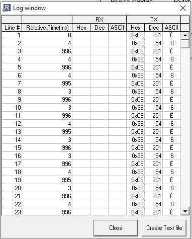
The gateway is transmitting the command to the sensor ( Now using RS232). The log shows the transmitions of the commands but not the reception
But all the time I have the invalid message number changing
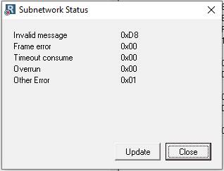
What the invalid message means?

![]()
Your sensor is connected to the bottom port?
And you are setting the serial settings here?
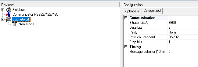
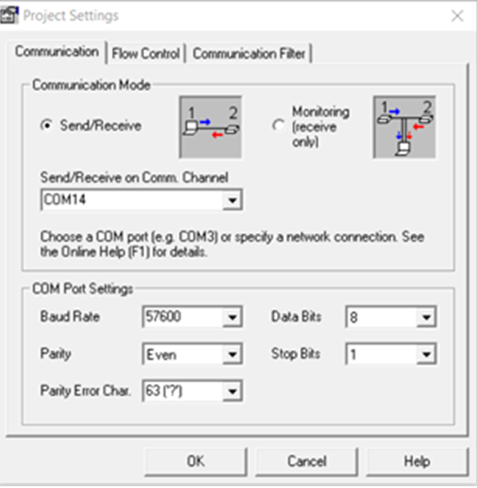
Hi Kyle, Yes, my sensor is connected to the bottom port. The setting of the subnetwork match with the setting of my sensor:
Bd. 57600
Data bits. 8
Parity. Even
Stop Bit. 1
Physical Standard. RS232
In the front port of the AB7010-B, I have connected my plc (Modbus RTU). My read and write blocks in the PLC are working correctly. Also, I seeing the commands
from the PLC in the Output Data of the ABC internal Memory.
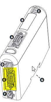
I have a more basic question, The electrical connection of the sensor based in the manual is:
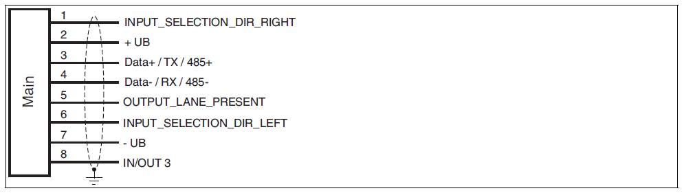
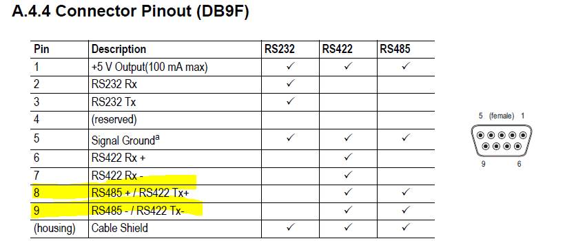
Based on the AB7010 manual, I was connecting the pin3 of the sensor in the pin 9 of the gateway and pin 4 of the sensor in the pin 8 of the gateway. Obviously,
in the subnetwork configuration my physical standard was RS485.
With this configuration the com LED on the sensor was off :
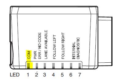
However, when I change the pin 3 of the sensor in the pin 2 of the gateway and pin 4 of the sensor in the pin 3 of the gateway and change the subnetwork
standard to RS232 the com LED start to flash.

I don’t have response data on the gateway and the invalid message is still changing with each command sent it to the sensor.
So I don’t know yet which is the communication protocol of the sensor.

![]()
Hi Lucy, I receive the one from you yesterday but with out any content. I have one question regarding the connection and protocol. The electric connection of the sensor is
RS485 2 wires but the communication protocol is RS232?
Regards,
![]()