AB7072 & Yaskawa YRC1000 Controller

Hello,
I’m currently trying to communicate a Yaskawa YRC1000 controller(Ethernet) with a ServoTrack controller(Modbus RTU) using a Anybus 7072.

Im trying to read values from the YRC1000 and write them on the ServoTrack.
I’ve seen some videos, but most of them are limited to the configuration of the Anybus Device. Is there any other material i could check?

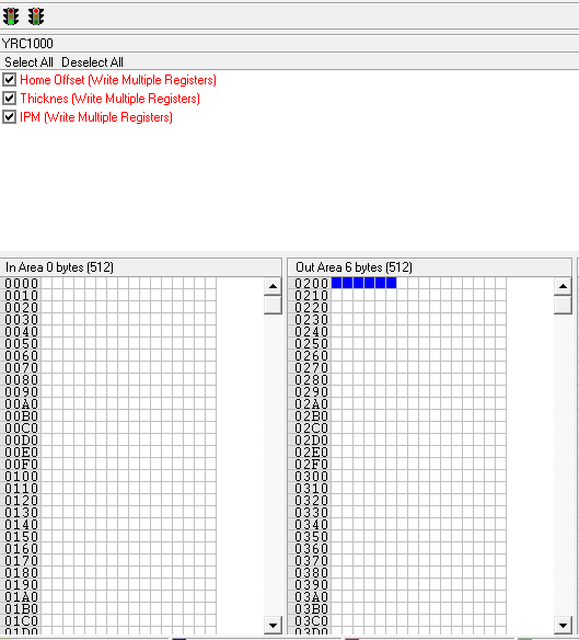
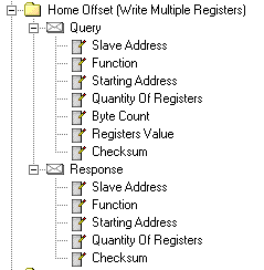
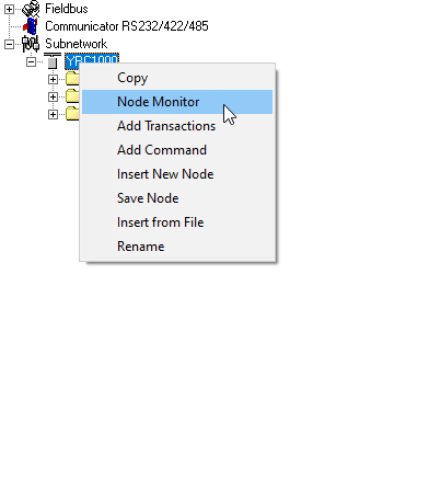
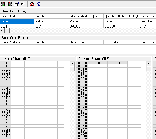
I was able to do the whole configuration. But I have no clue on where to do the whole setup for the YRC1000 on the AB7072 (Adresses, IP, etc).

YRC1000 V2.cfg (16.0 KB)

Hello @FelixVL,

Can you provide any context to this configuration? Were you already working with someone here in support? Do you have any questions that we can assist with?

Deryck

Hi Deryck,
Sorry looks like my whole explanation didn’t make it through.

I haven’t work with anyone here.

Right now i’m trying to communicate a Yaskawa YRC1000 controller(Ethernet) with a ServoTrack controller (ModBus RTU) with an Anybus 7072.

I want to read values from the YRC1000 and write them on specific modbus registers on the Servotrack. Is this even possible? My configuration makes sense?

I saw several videos, but most of them are only related to the configuration of the Anybus device. I’ll like to know if there is more information of what comes next. As I have no clue, on what adresses I need to configure on the YRC1000 to be able to write to the AB7072.

Regards,
Felix

Is there anything else i

Hello @FelixVL,

Your configuration looks correct. It looks like you have writes setup for register 39 (0x27), 33 (0x21), 29 (0x1d).

I have this post here where I walk through an example: Modbus setup with communicator

The Fieldbus section is where you will configure the settings the YRC1000 will make a connection to the Communicator. Here you configure the IP address, mask etc. The AB7072 can have either a modbus TCP or Ethernet/IP connection. Do you know what the YRC1000 be using?

We have application notes for an Ethernet/Ip connection with Allen Bradly/Studio 5000.

For modbus TCP Chapter 2.5 of the User Guide provides the modbus register mapping with the memory of the Communicator.

Thank you Derick,
I was actually looking to write to registers 40,34 & 29 respectively, so i changed those.

The YRC1000 needs to use Ethernet/IP. I need to read values from there.

The modbus writing would be to a ServoTrack controller, on the registers mentioned above.

I don’t have any instructions for the YRC1000 software but you should be able to setup a class 1 or 3 connection to the Ethernet/IP interface using assemblie instances INPUT: 100 OUTPUT: 150 CONFIG: 1.

Deryck

Thank you Deryck,
By any chance you have any instructions for any other Yaskawa robot controller? DX200, DX100?
That could help me a lot.

Hi,

I dont have have any instructions for adding them to a Yaskawa. From some past cases I recall that they have an option for adding connections for ethernet/IP but i don’t know the process.

Do you have any option for adding an Ethernet/IP connection or message instruction? If you can provide a screen shot I might be able to help you fill it in. You might need to check with Yaskawa for documentation.

Deryck

Hello Deryck,
I’m finally able to continue working with this.

I’m still confused on how the communication is suppose to work.
I did the setup for the Ethernet/IP communication from the Yaskawa controller to the AB7072. I’m currently just working with outputs, I selected from OUTPUT 201.

I force the output on the controller to check if i could see something on the Anybus subnetwork monitor. But nothing showed up.

Where can i check on the Anybus which address am I suppose to use on the YRC1000? If i set an output on the YRC1000 that should be an input on the AB7072 and then another output to be written on Modbus RTU? Or how it actually works?

Regards,
Felix

Hello @FelixVL,

Is the device added to the Yaskawa as an IO device? The data shown in the node monitor is from perspective of the serial side, this means output from the plc is output is the output for the communicator. Memory byte 0x200 should be byte 0 for th PLC. You should be able to look at the transactions to see where in memory the data is mapped from.

Deryck

Yes I added the AB7072 as a Scanner on the Yaskawa controller, i set some inputs and outputs for it.

Thank you for the Memory byte 0x200 information.

Is there a way to see on the ACM the values i’m getting from the Fieldbus?
I’m checking the transactions that the Wizard gave me, but not of them seems to be displaying values.
image

If you look at the node monitor you will see the data stored in the communicators memory. Keep in mind the data will be displayed in bytes.

image

You can also use the logging feature to see the serial messages being sent and received. This should help identify any errors. The site simply modbus is a great resource when trouble shooting modbus transactions.

Deryck

So if it is not changing at all, even when I click refresh that means that I still have problems with my communication. Right?
image

I also tried the logging feature, but i’m not completely sure if the results make any sense.(File attached)

Is there any other way to actually test that the communication between the devices has been established?

log.txt (4.9 KB)

Hi @FelixVL,

Since this is output data it should be showing the data sent from the Yaskawa. I assume the 3rd picture if from the Yaskawa, I would expect the 127 data to show up in the node monitor. Does it show any errors?

Looking at the log it looks like the serial device is not responding either. Modbus devices always respond to a query with either the data requested or a error response. This could be an issue with the wiring, serial settings, or you have the wrong Node ID.

Deryck

Thanks @deryck_hms,

Yes the 3rd pictures is from Yaskawa. Basically I set the first 8 bits to be a byte to send them all together. And yeah, I would expect for the 127 to show up somewhere on the AMC software, but it doesn’t.
I didn’t get any error. As from Yaskawa is an Output, I can’t think a good reason for it to show an error. On the Anybus side, i got nothing either, but I’m not completely sure if there is another part where I can look for errors.

Sorry, the serial device is currently not connected, as it is being used as a stand alone device for test purposes.

This could affect what I’m seeing from Yaskawa? I wouldn’t expect to be the case.
My plan was to establish the communication with Yaskawa and then add the Serial device.