AB7318 - No Frames Being Placed on the Bus

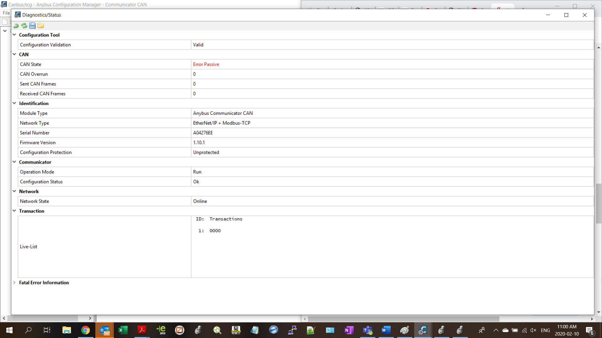
I’ve got an AB7318 connected to a 1769-L33ER PLC and no matter which method I try (cyclic or trigger byte) I cannot get anything onto the bus, judging by the line listener. I always have a “passive error”, no matter what I do. I have checked that my instance sizes line up; I have green lights on LEDs 1 & 2. LED 6 is also solid, and LED 5 is flashing green.

I’ve checked that my mapping between the PLC and AB lines up, I’ve been able to trigger reboots using the control word, but when I change the value of the trigger byte I get nothing on the line listener.

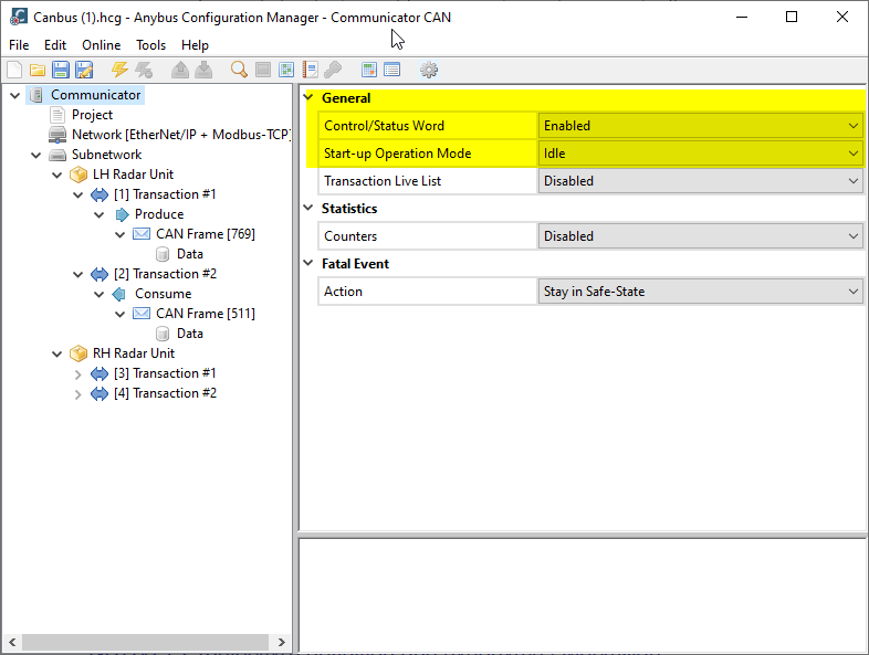
In trying to narrow the problem down, I unplugged the CAN connector from the Anybus, am I right to assume that I should still see frames from my Produce transaction?

Could it be my terminating resistor? Between current and past projects the electrical drawings indicate 120ohm resistor on the end of the bus cable, on the end and at the beginning of the bus cable, or no resistor at all. Could this be my problem?

Any ideas on what could be wrong, or tests I can do to prove out if I’m doing something wrong or if there’s something wrong with the module? I’ve included my PLC program and configuration for review as well.

Thanks
-Colin

Canbus.hcg (3.8 KB)TailLightTest.ACD (1.9 MB)

Yes. There should be terminating resistors on both ends of the bus. Please also check that you have the correct voltage on the CAN bus. Make sure the baud rate matches on all devices. Do you have a manual for the CAN slave devices? Are they CAN version 2.0A?

I wasn’t able to open the PLC project as my version Logix Designer is older than yours. Did you set up the AB7318 in Studio by importing the EDS file? Could you share a screen shot of that side?

In my case, both ends of my bus being the DE-9 connector at the Anybus, and where the end of the cable goes to the terminal block? I just want to be clear that I’ve set up a little test bench and removed my slave device to eliminate as many variables as I can, and I want to make sure that this won’t cause any additional problems. At this point I just want to see Produce transactions from the Anybus on the Line Monitor.

Baud rate on all devices being my slave device, and the Anybus? Or PLC to Anybus?

I actually don’t have a manual for the slave devices, that’s why I’m hoping to get it sorted without the slave device first. I’m using the PLC program from an old (working) project, with the Anybus Configuration from that same old project (the files I sent), just to get a working Produce transaction on the line before I adapt it to my current application so I can determine where any error comes from.

The files I sent I think is CAN 2.0A, I’m basing this off of the frame ID that was in the configuration being valid for an 11 bit identifier. I’ll toggle the option for 2.0B for the sake of ruling it out.

What’s the highest Logix version you have available? I might be able to save a downgraded copy. If not I can send a screenshot instead as you mentioned.

The Logix file is from a past project, so the module should be set up correctly as it was working when the project shipped.

Thanks,
Colin

Hello, @Colin_IAI,

I am reviewing this topic while Kyle is traveling this week.

If you had issues with Termination resistors you would have issues communicating on the bus but you should at least see the transmit messages on the line listener.

Looking at the config I see that you have the control/status word enabled along with the startup mode set to idle. Are you setting the control word to put the device into run? If not this is most likely why you are not seeing any traffic on the bus. As a quick test either set the start up mode to run or disable the control word all together.

Hi Deryck,

I’ll try toggling it to rule it out, but according to the Diagnostic screen I have it is in run mode:

I also put a 120ohm terminating resistor on the 9 pin connector between CAN +/-, as well as at the end of my cable. I measured 3.0V on CAN +, and 1.8V (it was 1.6 without the resistor at the connector side) on CAN -, which looks like it equates to logical zero, which I would expect in my case without anything happening.

This seems like progress, Error passive means it is detecting errors on the bus so it is not communicating. Are you sure the CAN settings are correct. This might just be caused from the bit rate not matching with all of the devices or the CAN ID is really 29bit not 11bit.

Deryck

If I’ve only got the Anybus on the line though, where would my settings be incorrect?

This is also a copy of the Anybus config and PLC from a completed working project about 3 years ago, so I would expect the settings to be fine. I did change from the 11 bit to the 29 bit just to check, no change though.

I’ve always had Error Passive using the trigger byte, it was only when trying to make an application cyclic did I get into issues with Error Active.

If Error Passive has to do with errors on the bus, let me make up a quick sketch so that we can be confident it’s not the wiring.

Maybe we should discuss this over the phone to better understand what is going on. Can you provide a number to reach you?

The error passive might be because it has nothing triggering communication.

Error Active is a bit miss leading, this means the bus is active and is not an actual error.

Deryck

That sounds like a good idea, I’m busy at the moment but I’ll send you a message with some contact info when I’m free. In the meantime, this is what I have going on with the wiring.

Topic closed due to inactivity.