AB7808-F Modbus RTU map

It is not clear to me what Modbus registers in the AB7808-F I need to query from my Modbus master to retrieve the data from a Profibus DP device. Profibus device is E+H FMU95 with 10 ultrasonic level sensors attached. Just need to read those 10 level values from AB7808-F Modbus registers.

I got the GSD file for the E+H device and used the Anybus NetTool for PROFIBUS to configure the 10 slots with AI(OUT) - not sure if this correct but there really is no other action I can do.

Anybus%20FMU95%20config

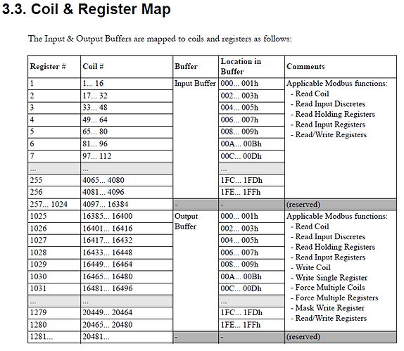
Here is the Modbus map from the Anybus Modbus RTU Network manual.

I don’t understand the correlation between the “input address” shown in Anybus NetTool and the Modbus map in the manual.

Hello @cgeorge,

The input Address location should correlate to the “location in buffer” in the memory map table showing what modbus address the data is located in.
so slot 0 is in input address bytes 0-4 or register 1, 2 and the first byte of 3.

Deryck

Deryck,
Thanks for the reply. I now understand the relationship between the input address and the Modbus map. This makes sense since 5 bytes are used by Profibus for a floating point value (4 bytes for value, 1 byte for status). See this table I created.

anybus%20modbus%20registers

The issue I see is that I want to make a Modbus query from a simple Modbus master (a data recorder) to the Anybus gateway, where I can specify the command (e.g. read holding registers), the starting register and the number of registers. For the AI1 value this is not an issue, as I can poll register 1 and 2 to get the floating point value. For the AI2 value though, the floating point starts at register 3.5 and ends at register 5.5. How do I send a Modbus command to read this AI2 value?

Hello @cgeorge,

Modbus is limited to the modbus function codes, reading registers and or coils, the mapping from memory to the registers is static. What you can do is move where the data is mapped on the master side to map to specific parts of memory. If you double click on the objects listed you can pick the starting location. This allows you to map the data to specific registers.

image

Let me know if you have any questions about this.
Deryck

Thanks Deryck. This may have solved my issue.

I skipped the byte after every AI status. This aligns each floating point value with a pair of Modbus registers.

anybus%20modbus%20registers_custom

I manipulated the start location for the input buffers for each AI.

Anybus%20NetTool_custom%20addressing%20setup

Anybus%20NetTool_custom%20addressing

Please advise if the Parameter assignment and Tag(s) tabs apply in my case. I have no information on the Parameter tab, I assume if available this would be populated from the GSD file?

Anybus%20NetTool_parameter%20tab

As I see it, now that I have assigned the buffer locations, I just need to poll each respective pair of Modbus registers for the floating point values. Please confirm.

Hello @cgeorge,

This is exactly what i was thinking you would be able to do. You now should only need to poll each register as needed.

The parameter assignments and tags tabs both should not apply to your use case. I typically don’t see customer using those features.

Regards,
Deryck