Anybus AB7832-F

Hi
i have an AB7832-F - I have configured the ethernet IP side ok, but i cannot communicate with the profibus side.
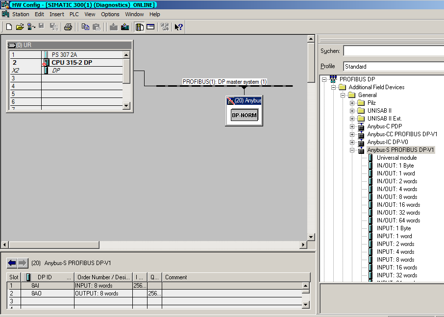
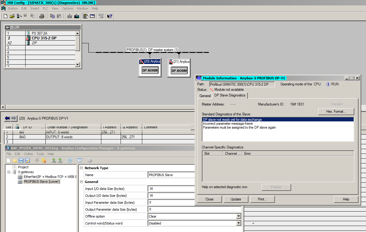
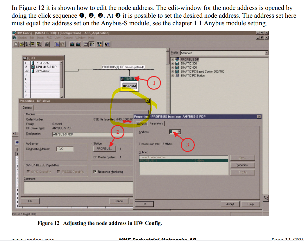
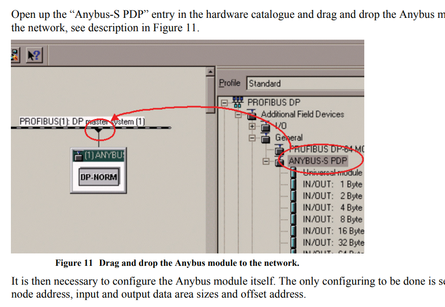
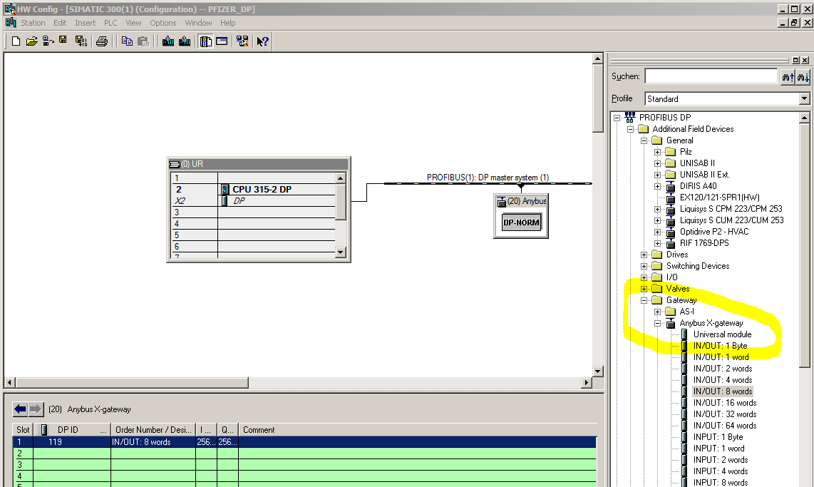
I have an S7315-2DP and i have added the GSD into the HW config and downloaded but doesnt communicate.
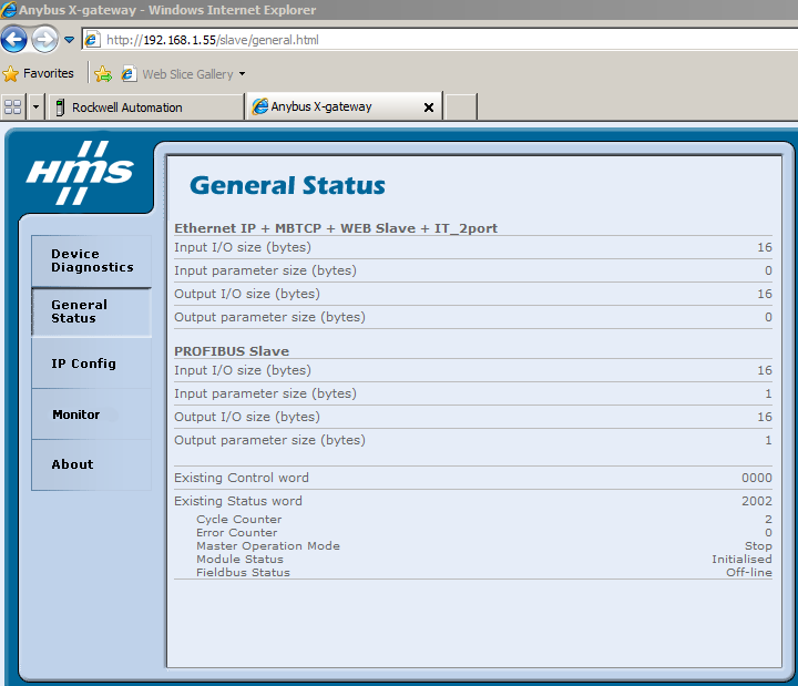
here is the General Status from the Anybus:
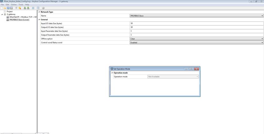
PROFIBUS Slave

Input I/O size (bytes) 16

Input parameter size (bytes) 1

Output I/O size (bytes) 16

Output parameter size (bytes) 1

Existing Control word 0000

Existing Status word 2002
Cycle Counter 2
Error Counter 0
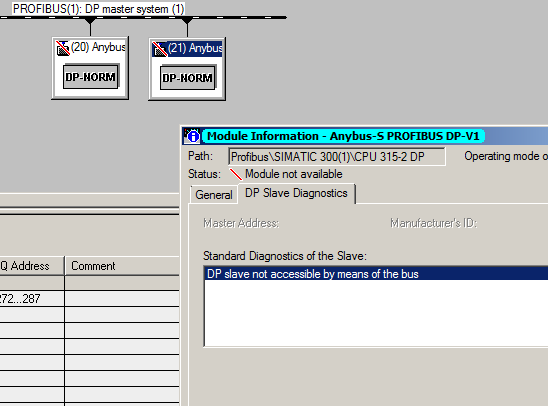
Master Operation Mode Stop
Module Status Initialised
Fieldbus Status Off-line

Can you please assist to configure this?
Thank you,

Are you using STEP7? If so, here are the instructions:

PROFIBUS_Slave_Step7_2.1.pdf (3.2 MB)

Here are the instructions for the X-Gateway configuration:

Check the wiring and LED status if you continue to have problems.

Hi Kyle,

Yes, I am using step 7 5.5 SP2

I have followed those manuals already. The profibus cable is good as I am using it to program the PLC.

Pfizer_Anybus_Initial_Config.hcg (4.02 KB)

Can you try disabling the Control/Status word to see if that brings it online?

Hi Kyle,

We had it like that to begin (no control/status words) and then we added them after, but it didn’t make any difference.

One other thing I tried Kyle, I tried to set the operation mode when connected online with the unit, but the operation mode option is greyed out – see here in the screenshot.

It’s strange that it’s still not running with the Control/Status word disabled. When they are enabled, you’d need the PLC to update the control word to put online, but when disabled it should just run. Can you let me know the color of each LED and whether or not it’s blinking?

You have completed the steps in the PDF above, given the Anybus a unique node ID using the switches?

Hi Kyle,

I’ve reset the configuration to scratch and repeated the setup again without success. I set the anybus to unique address 20.

If I check the DP Slave Diagnostics in Step7 it shows the 3 diagnostics lines, DP Slave not ready for data exchange etc.

image002.png

Hi Kyle

Problem solved….

The configuration does Not appear as per your documentation:

Your document Figure 11 shows the module under Additional Field Devices / General, however the GSD is actually Additional Field Devices / Gateway

image002.png

1 Like

Great! I’m glad you figured that out and thank you very much for letting us know what happened so we can update the documentation. Please let me know if you have any other questions going forward.

Kyle