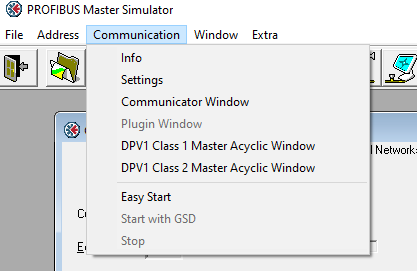
Also try using the Class 2 master option in our master sim and compare this with the RRTE. I expect this connection to look the same as the RRTE requests you see.

Also try using the Class 2 master option in our master sim and compare this with the RRTE. I expect this connection to look the same as the RRTE requests you see.
Good idea to reset the discussion. 
Ok… I’ve gotten things talking using the AnyBus serial to Profibus adapter – both Cyclic and Acyclic – and the Master Simulator.
I’m able to see cyclic data changing from my device, able to read and write to values no problem. No ADI below 256 as required.
The problems start when I try to communicate using a different interface than the serial to Profibus adapter.
The software I use to develop the ‘Device Description’ (DD) code, which is the code deployed to a customer’s Control System, cannot use the AnyBus serial to Profibus adapter.
It uses the Softing USB adapter. This tool includes a logging tool that shows the messages between the application and the AmyBus device, and I can see that there is a message to slot 1, index 0 that is being responded to. I can see that in the debug messages as well. But I also see in the logger that there is a message to slot 0, index 0. I believe this is a message requesting the ‘Physical Block’ – a standard block in Profibus DP. Since there is no response, I’m making the assumption (and I might be incorrect here) that this is why my DD is not working… I also have another application, Siemens PDM, which uses the same USB adapter. When I attempt a connection using this application, the errors I get indicate it can’t read the Physical Block. The Physical Block is located at Slot 0.
So I have tried to define an ADI for slot 0 (against the rule, I know) and have been able to read that slot 0 using the Master Sim with an Acyclic Read.
But with the USB adapter I do not receive a read to slot 0 (no debug message, no breakpoint). This is the thing I do not understand.
Unless there is something that the AnyBus module is doing internally to respond to Slot 0 itself without me defining an ADI at slot 0, I don’t see how this could work.
The question of ADIs less than 256 being a problem may point to something, but I can do a read with the Master Sim, and I am not defining Slot 0 as Cyclic.
-ed
Can you explain more about what the DD code is used for I am not sure if I have seen this before? Typically a profibus master is setup with the profibus masters configuration software where devices GSD files are used to that describe the devices and are used to map slave data to the Master.
I think Slot 0 as you mention is often used for Physical IO which might be why we recommend not using it. Do you know why your DD is trying to access data in slot 0 at all? It is still not 100% clear what your DD is doing or for. What is the actual error or issue with the request in your configuration? Does some configuration download fail? Perhaps no response for slot 0 is appropriate as no data exists there.
Deryck
Hi,
The DD ‘models’ the device.
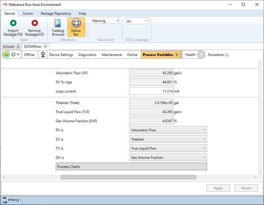
As a simple test, my Profibus DD is the simplest I could create. Display the ‘AI’ (Analog Input) block which resides at Slot 1.
The PDM or the RRTE application takes the DD, and using the GSD information to connect, reads data from the target.
This does not use any cyclic connection info from the GSD (so the module definitions are not used)
I’ve gotten a much more complex DD working with the HART protocol.
Here’s how the HART DD looks in RRTE:
Fancy.
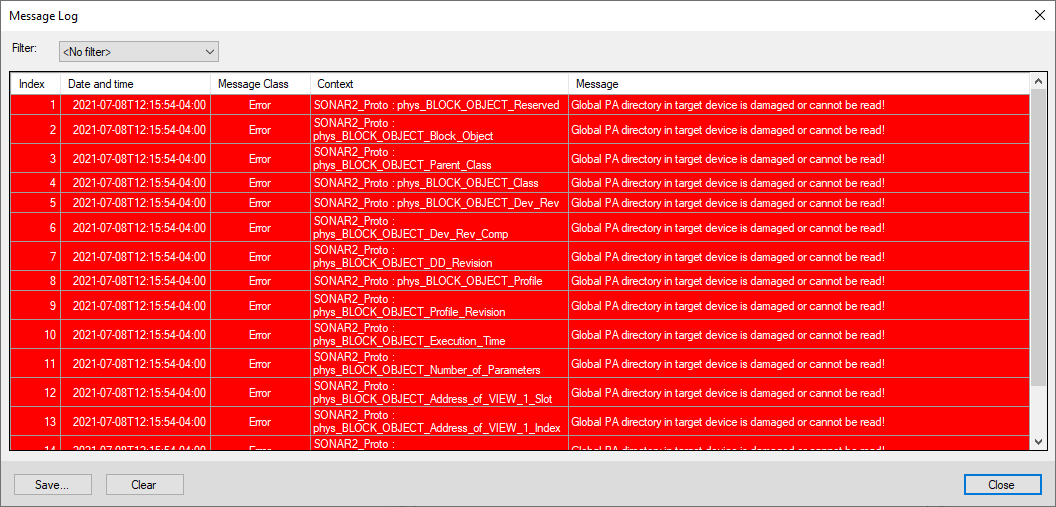
When I attempt to upload data from the device using PDM I can see in the debug messages from Anybus that I’m receiving the read of slot 1, but not slot 0, and the following errors are listed in PDM:
All indicating it can’t read the Physical Block. This is why I thought I needed to define slot 0. But doing so does not fix it.
(I get Anybus debug messages for any read to any slot/index if they are defined or not, btw)
I must confirm that the slot 0 read message is being sent by that USB device. I don’t think it is.
-ed
Do you know what class the Master for the RRTE or PDM is ? Do you know any more specifics regarding what it is doing for profibus messaging? Is it just trying to iterate through slot0 index 0 up?
Deryck
Hi!
I’ve literally just now had a breakthrough…. The response to slot1/0 needs to be an entire block of information – 20 bytes worth – that describe the AI block.
Then the master starts polling for more data! I can breathe again.
PDM is still not connecting, but this is a first step. I now need to figure out how to initialize all those values in the block so the polling is done properly, but at least I know communications is happening.
So in other words, there’s more to this than I thought.
I need to get some specs on Profibus itself and go from there.
Thanks!
-ed
Ok, me again….
I think I need some more information on this section. Perhaps an example?
Page 20 of the DPV1 Network Guide:
4.8 Parameter Read/Write with Call 4.8.1 General information Parameter Read/Write with Call enables addressing of ADIs based on instance numbers rather than Slot and Index. This is useful if the ADI implementation is primarily designed for a linear addressing scheme as used on most other networks. It may also prove useful when using masters with limited addressing capabilities for slot 0, since such masters may otherwise have trouble accessing ADI instances 1… 255. Unlike the standard DP-V1 Read/Write service, Parameter Read/Write with Call uses the Call application service. On the PROFIBUS telegram level, the Parameter Read with Call service request consists of a standard DP-V1 header, a Call header, and the ADI number. When received by the module, this is translated into a standard object request towards the application data object.
Is this something I need to enable or initialize somehow?
Perhaps this is why slot 0 is not responding?
-ed
I believe the Read Write call is just he queries as described on the following pages, they are just a different messages that would be sent from the master requesting specific ADI’s. It is not something you need to enable on the compactcom. I don’t think it is directly related to your issue but perhaps could be a workaround. I don’t have any examples besides the explanations on the pages following page 20.
Do you know what your masters, besides the Anybus master sim, is configuring for connections? This may help narrow down the issue.
Deryck
Hey there,
The master is not doing a cyclic connect, so I’m good there. The master however is looking for “Block” responses, which I need to implement.
And to do that, I need to find the specifications on them. This is my goal today.
Thanks,
-ed