Communication error with AC Unit Mitsubishi SEZ M50DA

Hello,

I have on my Intesis module a report for communication error with AC unit (register 11 and register 12). The status LED of the Intesis module also blink at the rate to signal communication error with AC unit.
I tried the different configuration for the AC indoor unit’s features (SW1 on intesis module) but as I suspected it does not change anything and the Intesis modules is still unable to communicate with the AC indoor Unit:

Here is my test system:

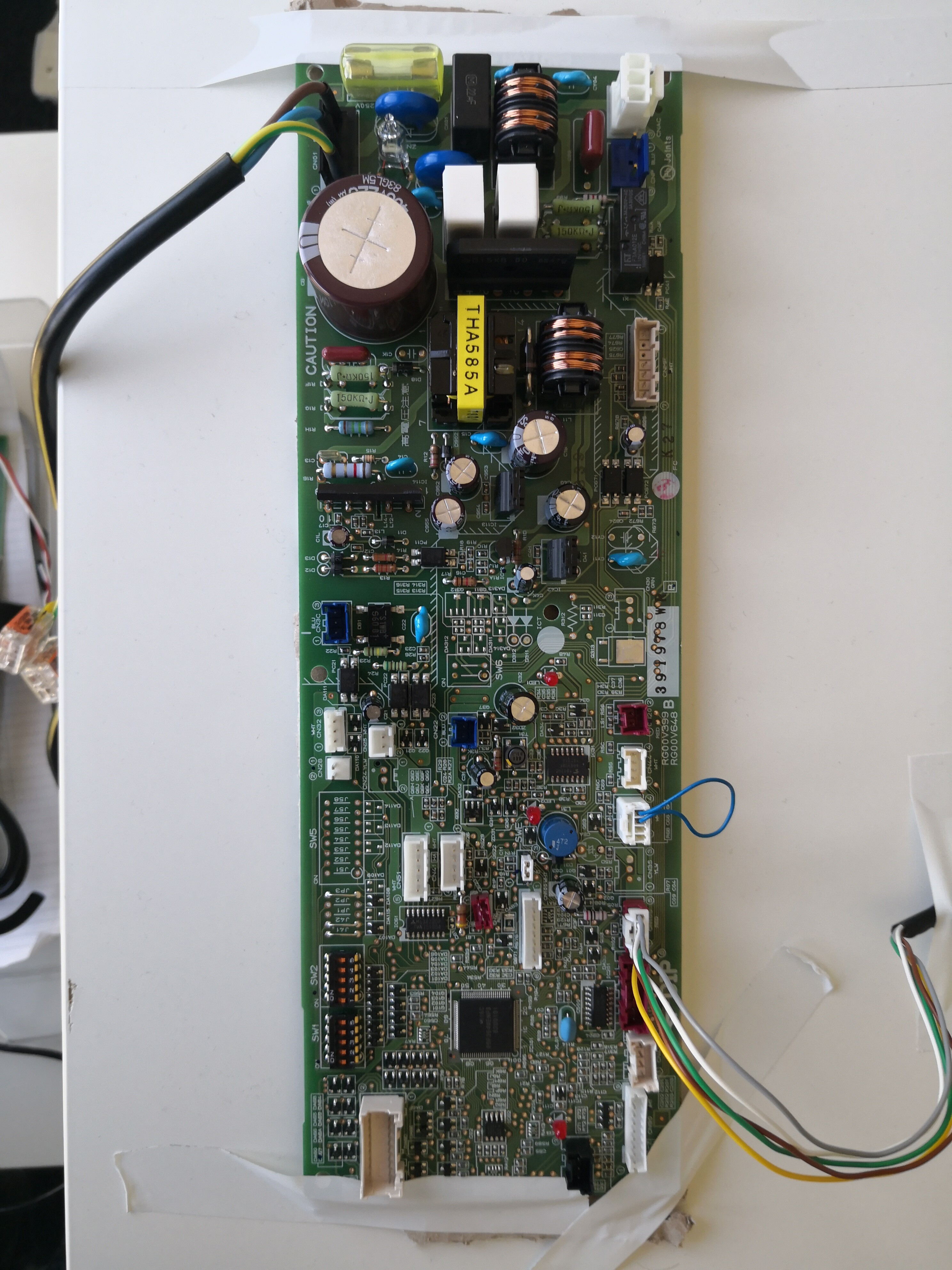
AC indoor unit (see picture):

  • SW1, SW2 All on OFF (I did not find any documentation about them if it’s the use case. SW1 model, SW2 capacity)
  • 240VAC on CNO1
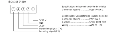
  • Intesis cable on CN105 to K1 on the Intesis module.

Intesis Module (INMBSMIT001I000):

  • Intesis cable on K1 to CN105 on the AC indoor unit.
  • SW1 All off (I tried different AC indoor features but it does not change anything)

Test result:

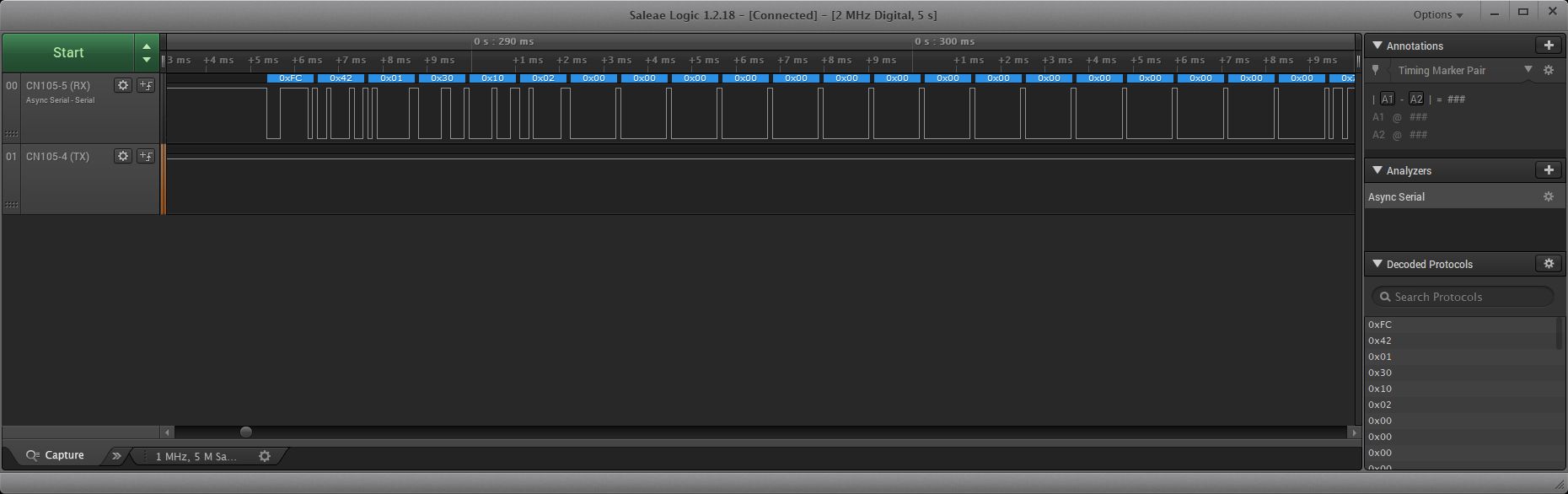
  • Read Intesis registers OK. (all different register I read is correct)
  • Write register almost OK. When I try to write a temperature set point (Register 5 of the Intesis module) the answer is correct. But if I read back the register I still read -32768 that is the “Initialization” value (I suspect it’s because there is no communication with the AC indoor unit).

Thank you,
Cristian

1 Like

Do you have an external temperature sensor attached to the AC unit? The initialization value states that there is not reference sensor to get the AMBIENT temp.

As for communications with the AC unit, are you able to set the fan speed?

I don’t have an external temperature sensor attached. In this case I’ll integrate the unit in a smart home system which has its own thermostat and with it I’ll do the automation of the AC unit (on/off depending on set point temperature or cool/heat etc. ).
I’ll check if I can change the fan speed.

Thank you

Yes, let me know if you are able to change the fan speed. I think the communication with the AC is fine, but youre getting the init error because of not having a sensor on the unit.

After some tests all the registers related to the AC (ON/OFF, mode, fan speed, set point) does not retain my written value, when I read it after the write I still have the default value.
What else could be the cause?

Could be a DIP switch setting on the board and/or on the Intesis module?

So on the Modbus side, it could baudrate and configuration issue. I posted the installation guide that outlines all the dipswitches.

Can you tell me what the dipswitch values are ?

SW1
SW3
SW4

Also, what is the serial configuration for the Modbus end?

Baudrate?
Stop bits?
Polarity?
Terminating resistor?

Also you can check the CN105 cable to verify there is voltage on that line.

Hello Kevin,
I introduce myself, I’m stéphane the actual engineer that is in charge of the firmware implementation to control the AC via the Intesis module.

To recapitulate my issue or no-issue.
I don’t have any problem communicating on the Modbus side. allis working, I can read and write registers inside the intesis module, I receive the expected modbus RTU frames from the Intesis module.

My problem is only that it seems there is no communication between the Intesis module and the AC indoor board. (and it’s the only part I have, I don’t have all the AC, and the indoor board is only connected to the main voltage and the Intesis module, there is no temperature sensor or anything else connected).

the SW1 is all OFF as I don’t really know how to set it as I just have the board and I don’t think it should cause a communication issue. ( tried the different AC configuration but there was no change)

I did not find any specification about the communication or the connector pining between them (CN105).
The Intesis is powered… but it say there is a communication issue. If I had more information about what kind of signal I should find and where (RS485, UART-TTL, etc) I could measure the signal.

I hope the problem is more clear?

Best regards.

Stéphane

Hello Kevin,
I had some other general question:

  • Do we have to “initialize” the AC at start-up like as to set the Vanes Position register.
  • Do we have or not have to do things when the AC report an error? Like to switch it OFF or not Switch it ON (by writing/ not writing in the corresponding register).

Hello,

I would check the leads of the CN105 cable to the AC Board. We have had issues in the past were the board fries, and communication is lost between the Intesis Unit and AC.

image

If the AC has an error, there isn’t much that can be done with the Intesis Unit to resolve it. The Intesis gateway is only used for communication. Only time a power cycle should be made, is when you change the dip settings on the Intesis Unit itself.

Thanks for the connector specification.
best regards.
If I understood correctly CN105.4 is TX (AC → Intesis) and CN105.5 is RX (Intesis->AC).
I measured the signal this morning with cables soldered on the AC indoor board, and it seems the AC is not answering to the Intesis

Hi Kevin.
Int the compatibility list for mitsubishi AC I fount here:

The model we will use is in the list (SEZ M50DA), but I don’t find it in the “available feature” chapter 6.
Which other model should I refer to? Or is it SEZ-KA…/ SEK-KC25

And Where do I find the corresponding model for the different values of the register AC Model (address 12)?

Hello,

You can use the compatability tool on our intesis site. You can get a full list of devices compatible for the AC model.

https://www.intesis.com/support/hvac-compatibility