
Can you give me an example of how to create a Modbus configuration in Anybus Configuration Manager?
Modbus Example for Anybus Communicator
Configure the serial side of the Communicator first because that configuration will determine the IO size to be used on the Fieldbus side.
Configure the subnetwork
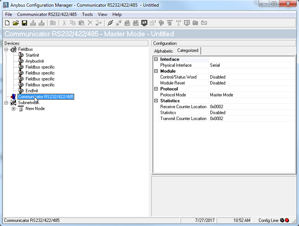
Set the communicator to Master Mode for Modbus communication. This is set under the ‘Communicator’ section in Anybus Configuration Manager.
Configure the serial settings like baud rate, parity, and stop bits in the ‘Subnetwork’ section.
Node and Transactions
‘New Node’ is the slave device that we are talking to. You can right click it to rename it or to add another node. Set the Slave address (aka Node ID) to the right.
Transactions consist of a Query (what is sent on the Tx line) and a Response (what we receive back on the Rx line). The built in Modbus transactions are called ‘Commands’ and can be added by right clicking on a Node and selecting ‘Add Command’. This will list all available commands. Double-click function code 3, ‘Read Holding Registers’ to add the command to the Node.

Read Holding Register (Function Code 0x03)
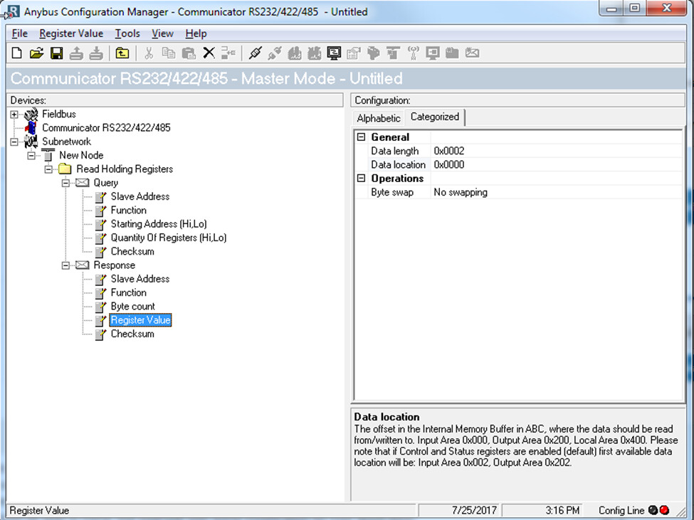
Expand the Query and Response to see what each is comprised of:
| Query | |
|---|---|
| Slave Address | Copied from node |
| Function | Auto filling from command |
| Starting Address | Starting address you are reading from the slave |
| Quantity Of Registers | Number of registers being read from the slave |
| Checksum | Auto generated |
| Response | |
|---|---|
| Slave address | Copied from node |
| Function | Auto filled based on command |
| Byte count | Number of bytes the slave will be responding with |
| Register Value Register | Address where the response is stored on communicator. This will also correspond to the address you will read on the fieldbus |
| Checksum | Auto generated |
In this example, for the Query we’ll set ‘Starting Address’ to 2 and ‘Quantity of Registers’ to 1 because we want to read the second register only. For the response we’ll set the byte count to 2 bytes which is equal to 1 16-bit Modbus register. Since this is our first read request, we’ll leave the data location as 0x0000. If we were to add a second read command, we would offset the next location by 2 bytes (0x0002).
Read Input Registers (FC 0x04) works the same as Read Holding Registers (0x03), it just writes to a different area (depending on the node).
Write Single Register (Function Code 0x06)
The ‘Write Single Register’ command is like the ‘Read Holding Register’ command, but instead of requesting an input, you are sending an output to the subnetwork. This is a value you write to the communicator from the fieldbus network. In our query, we are setting the ‘Register Address’ to 5. In ‘Register Value’ we’ll set the Data length to 2 and Data location to 200. The output registers start at 0x200.
In Modbus, the node sends back an echo of the request, so we need to configure the response to match the incoming data. In the response we set the Register address to 5 matching the query. Since we are expecting the response to be the value we just wrote, we’ll write the data to the general section. This can be used for trouble shooting purposes later if needed. The data length is set to 2 and location to 0x400.
Write Multiple Registers (FC 0x10) works the same way except you will find an additional field for ‘Quantity of Registers’.
Update Modes
When you click on ‘Query’ you will see a field called ‘Update mode’. By default, this is set to ‘Cyclically’ which means it will send the query repetitively every predefined number of milliseconds. Each 1 represents 10ms and the default setting is 100, so the query will be sent once every 1000ms (1 second). There are 4 different Update modes:
| Cyclically | Transaction is issued cyclically at specified interval |
| On data change | Transaction is issued when a change in data is detected |
| Single Shot | Transaction is issued once at start up |
| Trigger | Transaction is issued when the trigger byte value has changed |
The trigger option allows you to send the query only when you want to, upon an update of the trigger byte. You will need to specify a trigger byte address for the query in the Output area (0x200 – 0x3FF). When you want to send the query, you will update the data associated with it (the data to send) and then write to the trigger byte from the Fieldbus side. Each time you write to the trigger byte you should increment it by one.
1 Like