
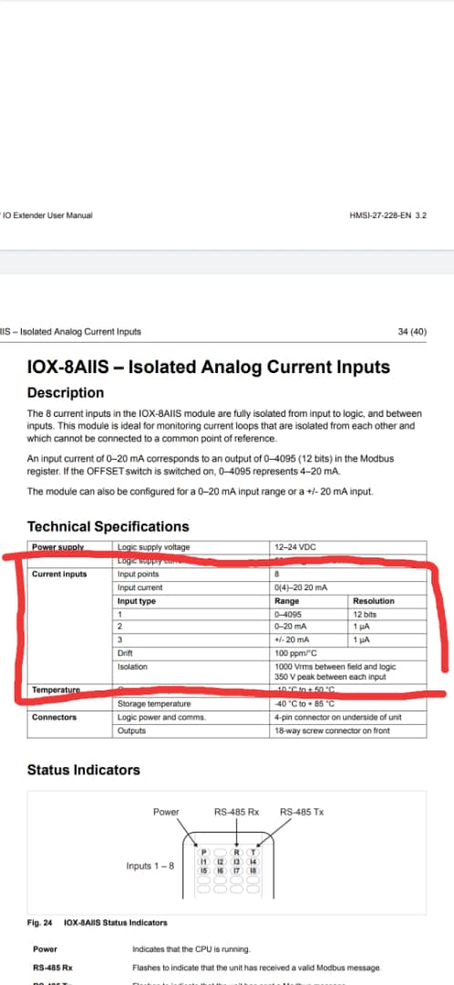
Anyway why cant we use 0-20
Hi Tims we have a couple of questions to ask
-
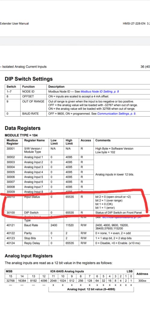
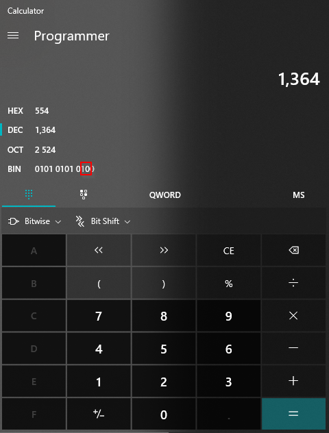
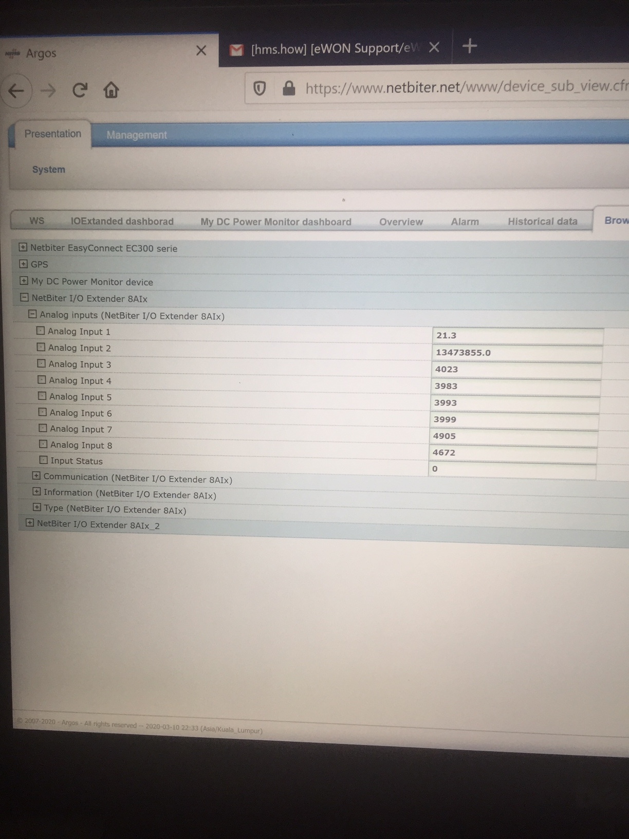
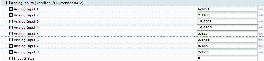
Input status : how to determine bit 1 or bit 2 ours is always=0…see column circled in red
-
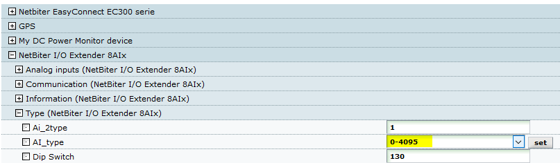
We are not sure how to set input type 1 , 2 or 3
Hey Zakaria,
I was just taking a look at your setup. It looks like the 0-4096 wasn’t set, after making that change it looks like it’s reporting the correct values. If you then want to convert it from a range of 4-20mA you’ll need to do a conversion where you multiplying it’s values by 20 and dividing by 4096.
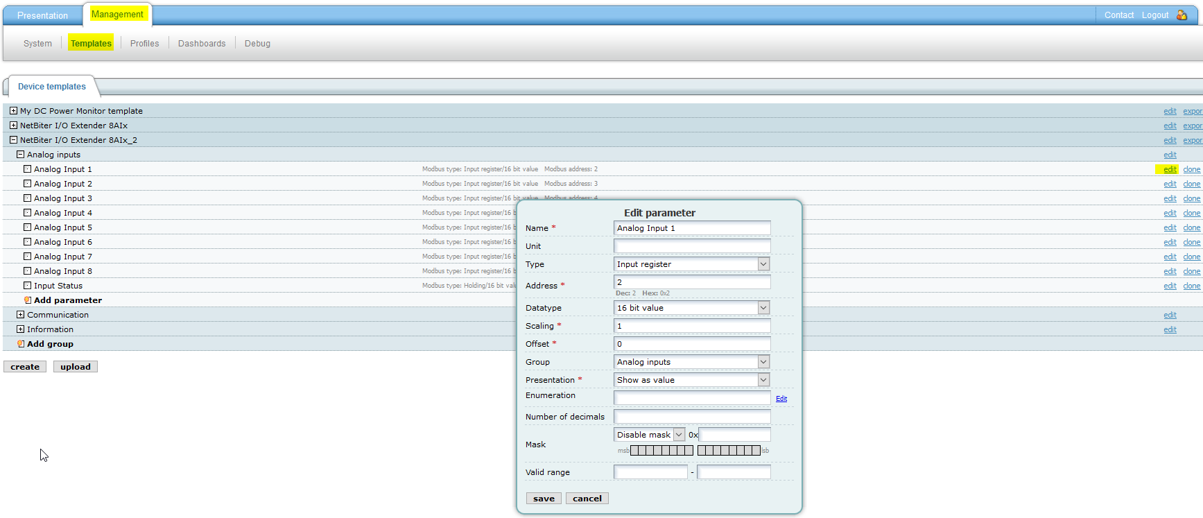
It looks like you also have duplicates on your template for the second 8AII
As for that input status, it might be showing a 0 because there’s nothing being read on a few of the Analog inputs and it might be viewing that as an open circuit
Hi Tim,
I think you need to explain a bit more. Since we totlally lost after the adjustment. Please refer to attached memo
azakaria
Explanation of the problems in using IO extender 8AIIX.pdf (437 KB)
Hi Zakaria,
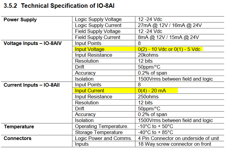
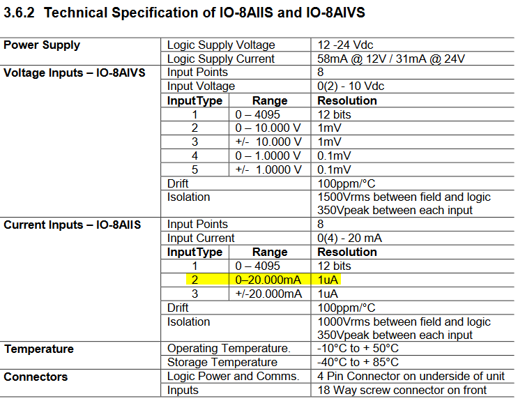
- In your pdf you say that the input voltage going into the device is 0-12V and the input current is 0-2A. You’ll want to be very careful with that because these devices are only rated for the following:
- It also looks like you said you were having trouble finding the user manual:
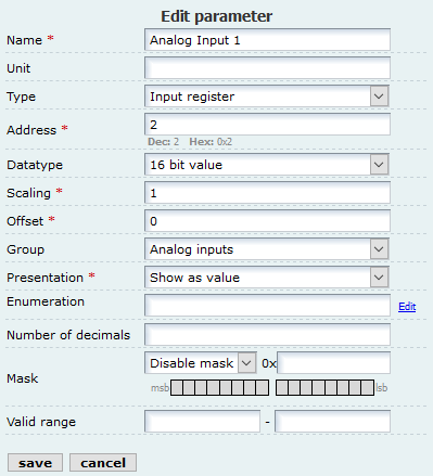
- When you said you were reading 5 digits, I believe it’s because you had it set to this setting:
- it looked like none of the values were going over 4096 when we changed it to type 1. Do you know what values you should be reading from this device? It looks like there was no change made in the scale for any of the analog inputs to do the conversion.
-
I’m not sure why we’re needing to have it in 0-4096 first, I would think that it would work when it’s set to mode 1 for 0-20mA but we were getting values higher than what the scale should allow so I wanted to see what the 0-4096 should be showing with the scale conversion.
-
What value are you showing for the turbine when it’s not running vs when it is running? If you disconnect the wiring from the turbine does the device read 0? Could you connect a Multimeter in between the IO extender and the turbine to verify that there is no current flowing when the turbine is not spinning?
-
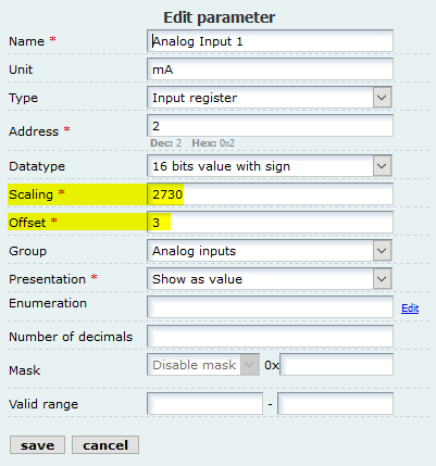
the only section you should need to change in the Edit parameters section should be the scaling. I can’t remember if it is multiplying the scale or dividing by the scale though. you should be able to put either 20/4096 in that field or 4096/20 and get the correct conversion.
-
to view bits 1 an 2 of the input status you need to take the number that’s being shown in the input status and take a look at it’s binary value:
Hi Tim,
yes correct, the input voltage and current from a turbine is 0-12V and 0-2A respectively but the one goes to IO8AIIXis 0-20mA . Because it comes from the voltage(0-12V input and 0-20mA output) and current sensor(0-2A input and 0-20mA output)
best regards
Just to make sure do you mean that you have some kind of converter that drops the 0-12V input into the 0-10V range and change the current from 0-2A to 0-20mA?
Yes precisely
Were you able to verify that there is 0 current when it’s not spinning, or check if the device is reading properly after changing the scale?
Okay we are checking it now, let u know the outcomes
Hi Tim, we have checked all the sensor outputs.
it is 3mA when the turbine not spinning. I need you a favor , can you please assist us to set the parameters so that the system read 04-20mA. In your last email you did not explain how to set those parameters.
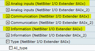
You can delete the existing Input type template and create a new one. So that we work from there.
kind regards
azakaria
Hi Azakaria,
In the previous email I went over how to set these up to read 0-20mA. Please see the section below:
the only section you should need to change in the Edit parameters section should be the scaling. I can’t remember if it is multiplying the scale or dividing by the scale though. you should be able to put either 20/4096 in that field or 4096/20 and get the correct conversion.
Sorry Tim, it does not work either ratio. 20/4096 or 4096/20. The turbine spins very slowly but after conversion it shows max, pl see the photo we just converted Ai 1 and Ai 2
When I took a look at your setup it looked like you didn’t have this set from 0-4095
I’m also not sure where the scale or offset on this came from on one of the examples you had setup
If the values are still going over you could also go enable a mask that blocks out the bits higher than the first 12.
Hi Tim,
we have tried to use your conversion factor either 20/4960 or 4960/20. but it didn’t work. The one you see is another factor we used by trial and error hoping to get the right answer.
Now as I said in our previous email, we did not know the correct procedure for setting the input type, we tried but it did not save. Can you set it for us again.
Also from our observation , your last setting (0-4096) did not generate (0-4096) but the analogue inputs are still reading 5 digit numbers. That’s why we tried many other ways.
I would propose you
-
delete our input type template and
-
create new template with your own setting.
it is much easier to start from there because it looks like we have some miscommunication somewhere.
I think it should work now. Can you check if your current readings seem to be correct now? These are the settings I used
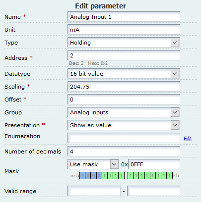
It looks like they’re all falling in the range of 0-20mA
Well it looks okay, let us verify with our remote camera
Well everything looks perfect for 0-20, but our sensor output 3-20. Can we just add no 3 in the offset column,
Thank you so much Tim


1 Like
I believe for this you would need to change the scale. You would now be having this be 4095/17 instead of 20 with an offset of 3
So this would be a 240.88235 scale with a 3 offset