MTCP flashing red on linking device

I am having this same issue (maybe I should have started new thread). Tried the above solution (firewall) unsuccessfully.
Using EN2MB-R (first application for me). AB ControlLogix PLC sending Alarm Code to PC with Video Camera control software.After connecting and configuring I get a flashing red LED on MTCP, and similar error as above (Technomanic) in Transaction Monitor. However, I am using Function 3 (Read Holding Registers). Not sure if this is correct, but don’t think it matters yet since I cannot connect.

HMS Firmware: 1.06 (have not updated)
HMS EtherNet/IP: 192.168.0.240
HMS Modbus Client: 192.168.0.241
PLC: 192.168.0.250
PC: 192.168.0.233

Modbus Server: 192.168.0.233, port 502
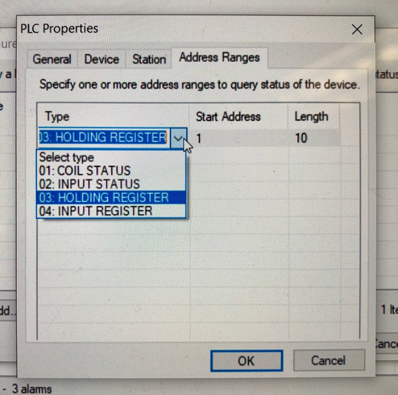
Server transaction: Function 3, UID 255, Address 1, uint16, Registers 10

All Ethernet cables plug into the same switch.
Can successfully PING both HMS IP addresses from PC.

Any suggestions appreciated.

What type of Modbus simulator are you using? The server would not be able to send a read command. Are you sure you are not using a Modbus client (master)?

The Red flashing MTCP light indicates a transaction error or timeout. If you are trying to Read Holding Registers from a Modbus Client (master), that would explain the problem. You need to be connected to a Modbus Server (slave).

Thanks Kyle for your reply.
This is my first time using Modbus, and don’t really understand the difference between client/master/server. I thought the HMS Modbus Client had to be the Modbus port on the HMS Linking Device? I have an AB PLC which will send Alarm numbers to Video Camera control software (IVC) on a PC. This Video Camera control software can be configured to ‘listen’ over Modbus TCP. At this point there won’t be any data going the other direction (from PC to PLC).

I’m open to suggestions. What I have is not working.

Thanks

This is correct. The client is just another word for master in Modbus TCP lingo.

So the HMS Linking Device (client/master) is what needs to be configured to send out the commands. You can configure it to update the alarm numbers, either cyclically (every x milliseconds) or on a trigger or data change. This will be a write command sent to the IVC. The Anybus Configuration Manager software (using the add-on profile) will map these registers to tags in your PLC. If you have the Modbus map for IVC (should be in the user manual), I can take a look to let you know specifically which commands you will need to use.

Kyle

Ok, thanks. I will be tied up until this afternoon. I will look up the Modbus map for IVC and let you know (I think they only use function codes 1-4, but will verify). Thanks again for your help.

Ok, I looked at the Modbus map for IVC…

As I suspected, only function codes 1-4 are available on the IVC. Those are all READ functions, right? It is currently setup to use function 3 HOLDING REGISTER. This is what they told me to use.

Klaus

Can you provide the user manual? In order for you to be able to use the EN2MB-R, the IVC will need to be capable of being a Modbus server that can be written to. If it can only act as a Modbus client, you are going to need a different device, like the AB7632.

Oh, that would be disappointing.
There is no manual, only a help menu in the software and tech support. I will try to forward your question to the IVC tech support. Stay tuned…

Kyle, as you suspected, the current version of the IVC software has the Modbus client only. Apparently two options are on the way this month. The new version of the IVC software will have the Modbus server and Ethernet/IP.
Thank you for your help on this. We will wait to see if the Ethernet/IP works for us. If not, then we may look into the AB7632 device.

Also, the EN2MB-R will work with a Modbus TCP server. I’ll close the ticket for now, but you can still respond any time if you have additional questions.

Thanks!

Kyle