Tried settings this to cyclic update as well and it didn’t help. I verified mapping is correct to the AnyBus as I was able to monitor a frame to send and it is updated in the Monitor/Modify window but nothing in the CAN Line Listener
I verified that the baud rate set the same on the AnyBus and CAN device (500bit), device is in run mode (control byte disabled).
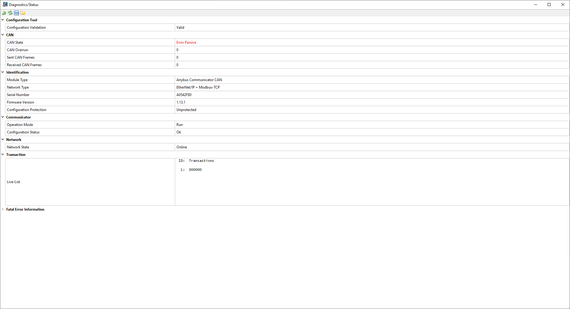
This sounds like a connection issue. The device will not be able to send frames if there is not a proper CAN connection detected. What are the LED status’ on the CAN Communicator?
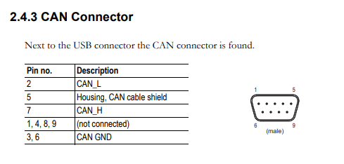
What type of wiring are you using? Are you certain that CAN_H is going to CAN_H and CAN_L to CAN_L as shown in the pinout?
There is only so much you can do with just a multimeter, you need a scope to see the actual the waveforms, but at least you can make sure the resistance is 60 ohm.
If the cable is disconnected at the Anybus module or if the Anybus is powered off then we do get 60ohms between CAN_H and CAN_L. Once the anybus is powered on then we get an OL on the multimeter.
I tried measuring voltage between CAN_H/ground (0.13V) and CAN_L/ground (0.12V)
The resistance is correct. You won’t be able to pick up the changes in voltage with a multimeter though.
What is the CAN device that you are connecting to? Do you have any other way of testing it to see if can communicate on a CAN bus? It sounds like there may be something wrong with it or the way it’s set up.
It is a Hamilton Zeus dispense device. I’ve tried two different ones so I don’t think it’s the device but could potentially be setup. I don’t have any other way to test the communication
Just to provide an update on this, it was an issue with the device. It was getting some power but was under the voltage it required. Once that was fixed I was able to get it to respond to the commands.
A few other things I noticed though
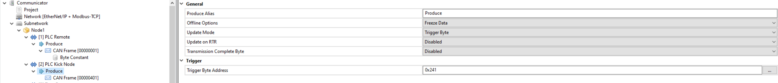
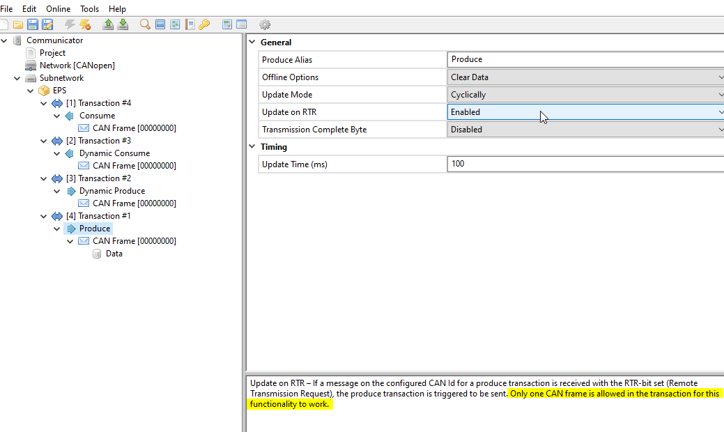
RTR bit of a dynamic produce is bit 5, not bit 4 like it says in the manual
Trigger byte for the remote frame coming back from the Zeus doesn’t work. I tried using a regular consume as well as dynamic consume. Through reading other forum posts it seems like this is a known issue
One other thing that I am having an issue with is sending a remote frame without using a dynamic produce structure as I’m wanting to send the remote frame for multiple nodes with the same anybus adapter. Is there a way to configure this frame using the regular produce?
I’m not sure I understand the question completely about sending remote frames to multiple nodes. Do you need to differentiate which node is responding? What is the reason for not using the dynamic produce?
I’m not very familiar with the Zeus protocol, so please be explicit about what you are trying to accomplish.
Keep in mind also, only one frame is allowed in the transaction:
Yes I did see that post about the RTR issue, the firmware is already 1.13.1 but the problem mentioned in that post is different than the one I’m experiencing (though this one doesn’t seem to be fixed either). I did find a workaround for this problem by setting up a transaction byte on the kick instead of activating a trigger byte from the remote frame.
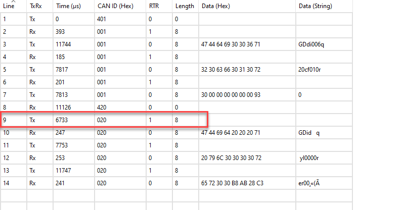
With the Zeus modules it needs the RTR when sending a a remote frame back to the Zeus. The Zeus sends a kick, PLC sends remote frame with RTR enabled, then Zeus sends data. It seems that in order to send a frame with the RTR flag high it has to be done through a dynamic produce.
The reason I didn’t want to use a dynamic produce was because we are needing to send these remote frames to 8 nodes. I’m able to configure the dynamic produce for node 1, send the remote frame, receive data, and repeat until all of the data has been received, but then I have to reconfigure the produce for node 2, send remote frame, receive data, and continue on for all 8 nodes which takes numerous scans through the PLC to update. If I was able to send the same frame with 8 different regular produce transactions then everything on the PLC side can be done all at once.
I understand. There doesn’t appear to be a way to do this for multiple nodes with this device at the moment. I can check with the product manager to see if they have any suggestions.