Problems with HMS-EN2SE-R

Kyle,

Is this going to require a download to the PLC for every little change I make to the serial network?? That will make this extremely difficult to accomplish in a timely manner.

Is it possible for the module to act as something other than a remote I/O type of module?

Thanks,

Ross

Unfortunately, yes it does require a download to the PLC because the tags are changing and need to match in both the gateway and the PLC.

I’m not exactly sure what you mean, but the device is limited to the way it is configured with Studio 5000. There is no other way to configure it.

I would recommend using a Modbus master simulator, like CAS Modbus Scanner to test all of the transactions (commands) with your Modbus slave, so that you will know exactly what needs to be configured in the linking device. That should save you have to do a bunch of troubleshooting and multiple downloads to the PLC.

Kyle,

Because it is so difficult for me to arrange time for a controller download, I am trying to cover my bases, and just read a large chunk of input registers AND holding registers, hopefully enough to cover all the data I am looking for.

My serial ‘subnetwork config’ appears to be valid, but when I download it to the module, and try using the Node Monitor function, all I see are zeros. Does this monitor tool not function if the module is NOT online with the PLC?

Thanks,

Ross

Hi Ross,

You don’t need to be online with the PLC to use the Node Monitor. I would suggest making a log with the Config Mgr or using a Modbus scanner to troubleshoot the Modbus commands and see why you aren’t getting a valid response. You can find the error codes at http://simplymodbus.ca/exceptions.htm

Kyle

Kyle,

Not to hijack or piggyback, but I am having a very similair issue. Can I share my datalog with you and see what we cna do to troubleshoot?

Thanks!

Please share on the other thread:

Kyle,

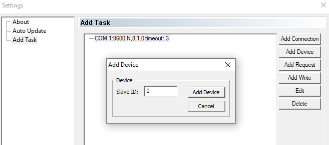
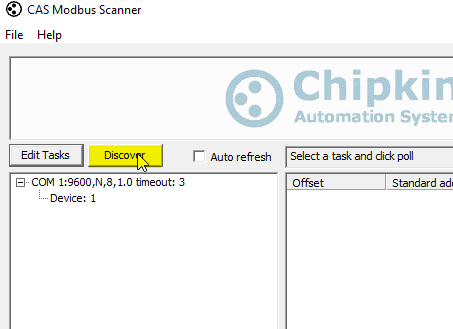
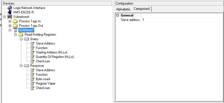
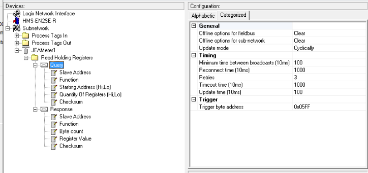
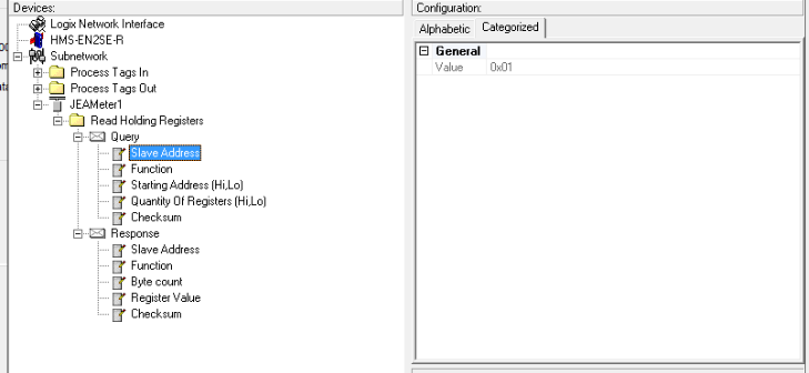
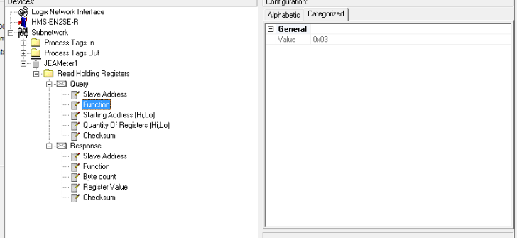
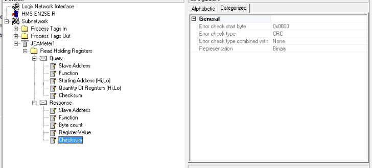
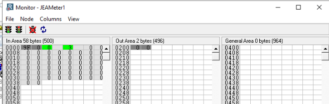
I have reconfigured this system to use a local CompactLogix CPU to connect to the HMS gateway. The CPU seems to communicate correctly, but I am still having difficulty with the ModBUS side. I used CAS Modbus scanner to connect to the modbus device locally,
and here is the series of messages I received while trying to read coils, inputs regs, holding regs, and status regs:

"[14:16:44] Recv error: Exception Response:

The device responded but with an error instead of data

0x02 - ILLEGAL DATA ADDRESS

The data address sent in the query is not an allowable address for the server (or slave). More specifically, the combination of reference number and transfer length is invalid. For a controller with 100 registers, a request with offset 96 and length 4
would succeed, a request with offset 96 and length 5 will generate exception 02. A request for offset 200 will also produce this exception.

[14:16:11] <= Response: 01 84 02 C2 C1

[14:16:10] => Poll: 01 04 00 00 00 0A 70 0D

[14:16:06] Recv error: Exception Response:

The device responded but with an error instead of data

0x02 - ILLEGAL DATA ADDRESS

The data address sent in the query is not an allowable address for the server (or slave). More specifically, the combination of reference number and transfer length is invalid. For a controller with 100 registers, a request with offset 96 and length 4
would succeed, a request with offset 96 and length 5 will generate exception 02. A request for offset 200 will also produce this exception.

[14:15:59] <= Response: 01 83 02 C0 F1

[14:15:58] => Poll: 01 03 00 00 00 02 C4 0B

[14:15:53] Recv error: Exception Response:

The device responded but with an error instead of data

0x02 - ILLEGAL DATA ADDRESS

The data address sent in the query is not an allowable address for the server (or slave). More specifically, the combination of reference number and transfer length is invalid. For a controller with 100 registers, a request with offset 96 and length 4
would succeed, a request with offset 96 and length 5 will generate exception 02. A request for offset 200 will also produce this exception.

[14:15:46] <= Response: 01 82 02 C1 61

[14:15:46] => Poll: 01 02 00 00 00 02 F9 CB

[14:15:46] Connect to COM 4:9600,N,8,1.0 timeout: 3

[14:15:36] Ready…

[14:15:36] Starting up…"

Can you make any sense of this?

Thanks,

Ross

This message may include restricted, legally privileged, and/or confidential information. If you received this message by mistake please delete it immediately and inform us about it. This message will be considered as originated from Gerdau or its subsidiaries
only when formally confirmed by its officers authorized for that.

Este mensaje puede contener informaciones de uso restringido y/o legalmente protegido. Si usted ha recibido este mensaje por error, por favor eliminelo e informe de tal situación al remitente. Este mensaje solamente será considerado como proveniente de Gerdau
o de sus subsidiarias cuando sea confirmado formalmente a través de los representantes legales debidamente autorizados para tal fin.

Ross,

The good news is that you’re getting a response at least.

It looks like you are reading the wrong registers or using the wrong commands. Do you have a register map from the manufacturer of the slave?

Kyle

Well, not a very clear one. The techs that supply me with info aren’t well-versed in the subject.

I was told that starting with register “1”, I should read 8 data values of 2 registers each. At total of 16 registers, but I have no idea if they are input registers or holding registers.

Register 1-2 = Flow Rate per Hour

Register 3-4 = Flow Accumulated (total)

Register 5-6 = Flow Accumulated Today

Register 7-8 = Flow Accumulated Yesterday

Register 9-10 = Average Flow rate per day

Register 11-12 = Energy rate per day (BTU)

Register 13-14 = Energy today (BTU)

Register 15016 = System Pressure

I hope that helps you more than it does me!

Thanks,

Ross

It looks like you are doing everything correctly and not getting the data. Did you try reading 15016?

I would contact the OEM and ask them why you aren’t getting data back.

What is 15016??

From your previous post:

Oh, sorry. That was a typo. Should read 15-16 = System Pressure. Register 15 and 16 together…

Kyle,

Just to update and keep this thread alive, I had the supplier come on site once again, and demonstrate that they could read data from their device, even connected from the wiring at my end. However, using the same software and settings they used, I still read
garbage with my Laptop, and still get errors via the Anybus device. I am currently waiting the arrival of a different USB to RS485 converter to use with my laptop, so I can verify function at least to the terminal point in my equipment cabinet. There may
still be a question about the proper connections to the DB-9 connector on the Anybus device, but I’ll cross that bridge when I get to it.

Thanks,

Ross

Hi Ross,

Once you get a working USB-to-serial adapter, you should be able to use CAS Modbus scanner to do a “Discovery” and hopefully that will find these pesky registers.

Use “Device Manager” to confirm the COM port number for your USB-to-serial device.

Add your connection and your device:

image

And just click “Discover.”

image

Hopefully this gives you an idea of which registers are readable.

Kyle

Kyle,

I apologize for the delay in response. This project got pushed to the back burner for a while. I am now resuming my diagnostics.
At last, I have been able to successfully read data from the originating device to my laptop, so I know that the serial configuration settings and the wire is good. At least, up to the junction where I inserted my laptop in place of the HMS module. There is still a short pigtail up to the 9-pin D-shell connector that could be in question. However, I have tested the wiring with an ohm meter, and confirmed that the 2 wires I am using connect to pins 8 and 9 of the connector.

As of this moment, I have the module configured as shown:

An the Node Monitor function returns these values:

image.png

I need to confirm that the Tx/Rx lines are not reversed, nut is there anything else that you suggest looking at?

Regards,

Kyle,

A bit more info -

The Red light called ‘5 - Subnet Status’ remains solid red, no matter which polarity is connected at pins 8 and 9 of the connector.

Attached is a short datalogger file. Hopefully, it means more to you than to me.

Also, there are no bias resistors at my end of the wire, but I believe they are enabled at the repeater that feeds me the signal. The registers read correctly when I attached the laptop to my end of the cable, so I assume that no resistors are needed, but I will certainly take that under advisement.

Regards,
Ross

image.png

log-07212020.txt (2.51 KB)

Hi Ross,

The log you made is showing no response from the node. Can you please send me a log of the data you are sending and receiving using the laptop so that I know how we need to mimic them using the Anybus?

Kyle

I’ll try to get that for you today, if the rain allows.

AS I mentioned, there is still the possibility that the short cable with the 9-pin D-shell connector is not correct. AS I read the manual, for RS485, 2-wire communication, the signals should be applied to pins 8 & 9 of the connector. Can you confirm that is correct?

Thanks,
Ross

Kyle, here are a couple of data files saved from the ‘Simply ModBUS’ diagnostic tool. I was never able to make the CAS ModBus Scanner tool function.

Also, I did find a bad connection in the short cable to the 9-pin connector, but even with that corrected, the Subnet Status LED remains solid red.

SimplModbusDatalog 2020-07-22 08.47.10.txt (519 Bytes)

Simply Modbus Master Byte History.txt (774 Bytes)