AB7007-C EIP Gateway

Hello,
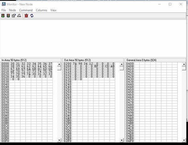
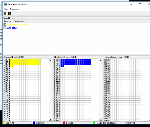
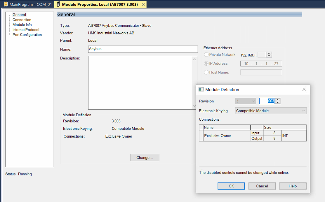
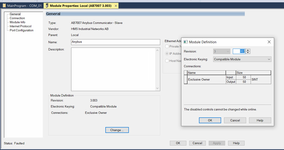
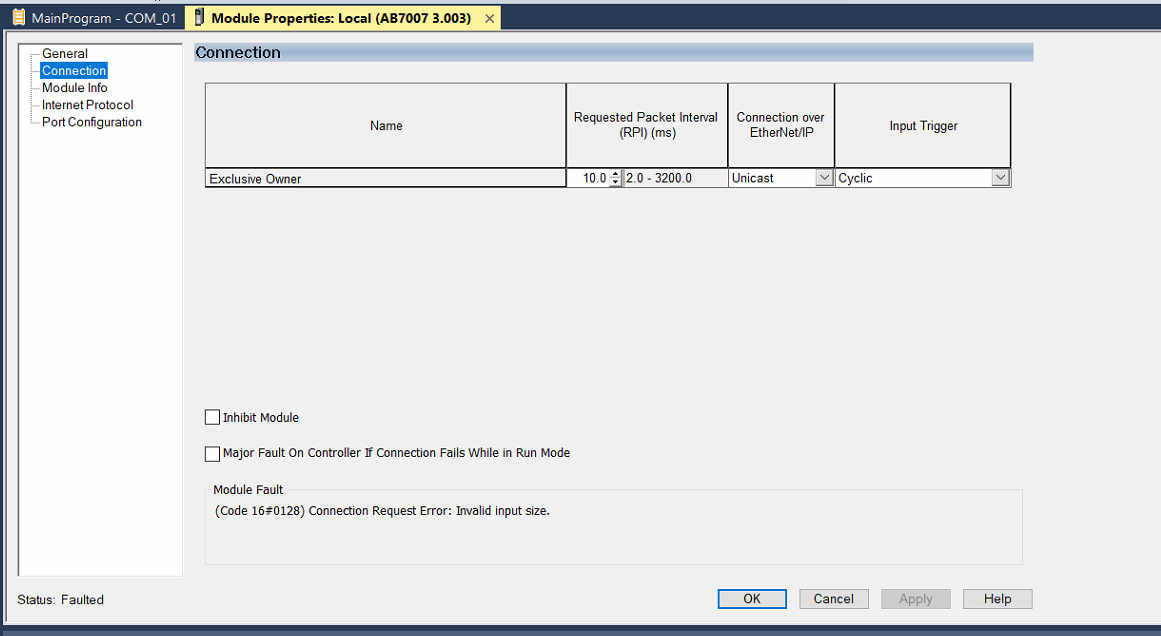
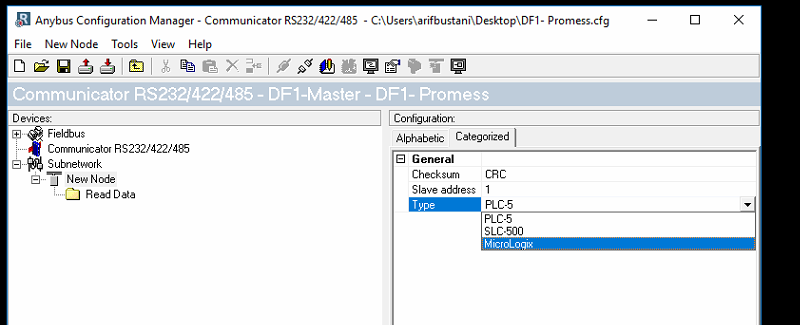
I am using AB7007-C (SN: 00029299) unit as an Ethernet/IP <–> RS232 gateway. A PC is on RS232 side and a ControlLogix PLC on EIP side. So far I can get the Node monitor to successfully show the messages I am sending over RS232 but not having much luck on PLC side. To start with PLC complained that ’ Module Revision does not match configured module’. I am wondering if the EDS file that I downloaded from your website is not compatible with the unit firmware?

Also in the Module properties window, I notice the following message ’ Module Identity: Mismatch’.

I would appreciate if you can guide me in the correct direction.

Make sure you are using the AB7007 eds and not the ab7072 EDS. you can download it here.
https://www.anybus.com/technical-support/resources/downloads-and-documentation?ordercode=ab7007

Also make sure you are using the latest version of the configuration software and download a configuration with it to the device.

1 Like

Thanks Deryck. The EDS file you sent the link for help resolving the issue. I was seeing my RS232 messages in Node monitor but now I can see it in PLC as well. Also when I sent messages from PLC it’s coming into my PC app and I can see the same in Node monitor.
So I notice that we have 512 bytes each of ‘In Area’ and ‘Out Area’ and 924 Bytes of ‘General Area’. My questions are as follows

  1. What is the purpose of ’ General Area’ and what is the use case for this memory location?
  2. _005A:AB7007_C5D4DDB1:O:0 << For reading from 7007 unit Logix designer creates datastructure of this data type. It has a Boolean to show connection status and an array of 16 SINT. The datastructure for output to 7007 is similar in type except the data type name is _005A:AB7007_E44F4328:I:0. Is it possible to increase the size of SINT array from 16 to higher? looks like the data structure is defined in EDS file or some place else. Logix Designer will not let me change the size of the array.
  3. Assuming that SINT array size can not be increased from 16 in the above mentioned two Datastructures , can you give me a hint to the mechanism I can use to transfer all 512 bytes into PLC memory most efficiently.

Thanks.

  1. This can be used to hand more complex messages where not all the data needs to be exchanged with the PLC but you are not able to use a constant.

  2. I am not really sure what you are asking here. You can increase your message size which will increase the allocated data that you would configure for the PLC connection. https://www.anybus.com/docs/librariesprovider7/default-document-library/application-notes/hms-scm-1202-056.pdf?sfvrsn=a64788d6_4

Keep in mind the communicator is handling the messages and the data is not exactly transparent from the EIP side to the serial side. I recommended reviewing the user manual sections that cover the message structure and transactions. For what you are looking to do you might be able to use a single transaction with a variable data object set to 512.

Thanks.
For Item#1 can you send me a link to an example?
I will try to explain what I mean for #2. In my Node setup, I have an Input size (Consum Transaction) that is 50 bytes long and the same size for Output (Produce Transaction). When I try to change the Module definition (pp 11 of 16 in PDF you sent the link) from Logix designer it only lets me define Input and out size to be maximum of 16 bytes long. Anything bigger shows up as a fault in PLC software whn PLC is put into RUN mode.
When the input and output size is left as 16 bytes I don’t have any fault and things are normal. ON my PC app I still read 50 bytes from Anybus gateway but only the first 16 bytes have data and the rest is NULL. Hope it is a bit clear now.
Is it limitation of the PLC interface or EDS file needs to be modified in order to use all 50 bytes of input and output data ?

I can provide a TeamViewer access to my system where i have this setup.
Thanks for your help.

It really comes down to the messages needed I dont really have a particular example to share. But lets say you received a message in ascii with TEMP:123OTHER:####TIME:12:34
If you dont know data would come following other you could use a data object to grab the data and write it to the general area and ignore it.

What do you have configured for your transactions? What size do you see in the subnet monitor?


I am guessing you have just one 16 byte parameter. Can you share your configuration. For me to look at?

Data Monitor


Promess config.cfx (392 Bytes)

No issues with communication but I am not able to configure more than 16 bytes (SINT) on PLC side. My App need 50 Bytes.

Hi @Utac_bustani ,

I would need to CFG file to see the configurations. The screen shot give me enough to verify the setup. You should be able to add it to the PLC with 50 bytes in and out. Change you share a screen shot of the definition? What errors are you seeing when you configure it for 50 in/out?

so in the previous post, I uploaded setup screen shots that work (with 16 bytes each) and Faulted setup with 50 bytes each. Anything more than 16 bytes is faulting the module interface. Let me know if you need more info.

Promess config.cfg (16.0 KB)


The error “invalid input size” is saying the size is wrong. Try downloading the configuration to the communicator again. If it is still not working change the protocol mode to DF1 download to the device then download your configurations again. This will have the software fully download the firmware and configuration to the device.

You want me to use DF1 even though the PLC is connected on Ethernet/IP port and PC is on RS232 of the device?


I am using RSLogix 5000. The drop-down menu on the configurator does not have that option.
Also, it’s not intuitive to use DF1 when I am communicating over Ethernet IP.

No, I was recommending to only do this then write your configuration back to the device. This would have had ACM download the firmware.

Looking back over you config i spotted the issue. You should set your IO size to automatic.

image

Yep. That resolved the issue. Thanks a lot.

Great! glad to hear it is working.