AB7697-F Configuration Help

I am attempting to configure an AB7697-F, Devicenet Master scanner in the upper slot, EtherCAT slave in the lower slot.

So far, I’m having trouble just getting the DeviceNet side set up. I can scan the DeviceNet network and see the devices (21 x Celerity/Brooks GF100 mass flow controllers and 6x Brooks PC115 pressure controllers).

Of note is that when trying to set up a scanlist and querying the gateway, the usb communication locks up intermittently. I’ve installed a relay so I can remotely reboot the gateway during development.

So, I have the EDS files loaded for both devices, but only the PC115 has a [Params] section. The GF100 has no [ParamClass] or [Params], only the [IO_Info]. (Both have the header [File] and [Device] sections).

I assume this is in some way responsible for the fact the GF100’s show up with a ? mark icon in the configuration manager and that when right-clicking on the device there is no properties menu item. Do I need to generate a parameters section for the EDS file to be able to switch to different inputs or outputs of the GF100? It seems like they can still be added to the scanlist, so I assume they are just going to the defined defaults (input2, output1).

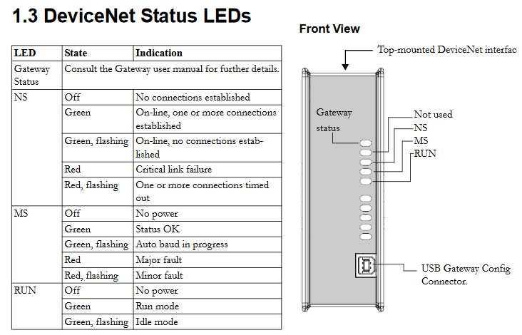
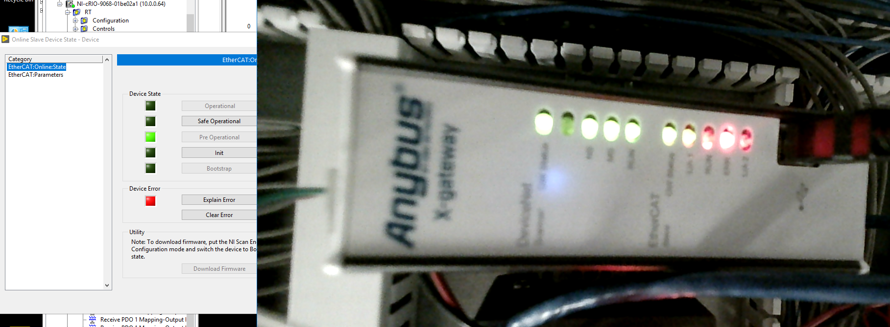
So, everything seems to be mapped, but the diagnostic tab says the device is not yet initialized, but the master state parameter is set to run. I can set that to idle, diagnostics goes to Programming Mode. Setting it back to run says device not yet initialized again.

I tried a restart by disconnecting the configuration manager and using a direct terminal connection and by power cycle, but it will seemingly not transition out of ‘not yet initialized’.

Just to skip ahead a bit, I have 78 input bytes and 52 output bytes, on the Ethercat side, is all I need to do is set the Input/Output PDO sizes to 78/52 (or maybe 100/100 for future expansion)?
At that point everything will be mirrored?

Looking through the example file for the OMRON controller, if I want to set up actual RxPdo and TxPdo mappings in the Ethercat ESI file, I should use an RxPdo index of x1600 and entry indices set to x2100 with subindices to map the individual bytes? (If that’s correct I assume TxPdo mirrors that).

Thanks for the help,
Mike

Is there an RS-232 interface on the gateway? (there are some different versions)

Have you tried connecting using the Ethernet Transport Provider?

Yes, the issue is most likely the EDS file. I would recommend contacting the OEM before changing it manually though, to see what they recommend.

Yes, just set the IO sizes (and offline option and control/status word if necessary) and download to the gateway. Add the gateway to the EtherCAT network using the ESI file.

I’m not exactly sure what you’re asking… You shouldn’t need to edit the ESI file. What software are you using?

No, it’s just the USB/Serial connection. The only ethernet port is for the ethercat gateway, I think. The transport path is COM-Port Transport Provider 10006 with the virtual com port selected that corresponds to the USB adapter (HMS Industrial Networks Anybus X-gateway USB-Serial Driver). Again, this is something I can work around as I need to since I can remotely power cycle the device now.

That’s their only EDS file, they had no recommendation either way. They were actually confused that there was hardware out there that needed the full [Device] description to match as their ProdType in their EDS file didn’t match the actual ProdType reported by their device. I had to change it by hand to get the gateway to recognize it. Any other clues as to what the ‘?’ in the configuration manager signifies?

I’m using an NI CompactRIO chassis which is a Linux RT controller with an FPGA onboard and can act as an Ethercat master. To get bytes in and out of an Ethercat slave, it needs RxPdo and TxPdo mappings in the ESI file similar to the example file you guys provide in one of your example downloads called ABXS_ECT_V_3_22_Fixed_PDO_256bytes_for_OMRON_1.xml. I’ve actually got the mapping layer working with my system, but I can’t get the Ethercat slave on the gateway to transition from safe operation to pre operational. I don’t know if this is a systemic issue or a product of not having the DeviceNet side in run mode.

I can transition between Init and Pre Operational with no issues. The only error I get trying to transition to safe-op is ‘Slave has thrown an emergency.’ Emergency code 0xA000, Emergency data ‘0E 64 00 64 00’.

On the DeviceNet side, I still have the problem with not being able to get it into run mode (get the message ‘device not yet initialized’ when querying the diagnostic tab). Should I try it without the questionable GF100’s on the scanlist?

Do you have the control/status words disabled?

For NetTool (Anybus Configuration Manager - DeviceNet) I would try, instead of connecting via USB, connect to one of the Ethernet ports and then in ‘Configure Driver’ select ‘Anybus Transport Provider’ and then ‘Ethernet Transport Provider’.

If that doesn’t work or if you are still having problems, than yes, I would try it without the GF100s to see if that works.

Have you ever set this GF100 device up with another master, using RSLogix/Studio, for example?

I’m not able to get to the system, I’m working remote, but I’ll reach out to the local tech to check.
None of the pictures in the manuals I have show an Ethernet port except on the Ethercat slave module (which, of course, is attached to the Ethercat network). There’s the USB connector on the front and there’s the Devicenet connector on top and there’s the In and Out ethercat ports on the bottom.

However, I don’t think the transport issue has anything to do with not being able to get the DeviceNet scanner into run mode. (I’m only getting lockups very intermittently now that I’m done with the initial scanlist setup) I haven’t used the GF100 with another PLC, but I was initially trying to use an NI DeviceNet module. However, I could not get that to work in I/O mode (could only get explicit messaging to work) and I needed the speed of I/O to get through the scanlist quickly enough (once per second, explicit messaging is pretty slow for this many devices). I was unable to get support from NI on the module so we decided to try a different tack with your gateway instead.

I’ll try with the GF100’s removed from the scanlist and see if that helps.

Okay, so removing all GF100’s from the scanlist lets me get the device into the running state.
However, this does not fix the Ethercat side issue of being able to transition to safe op or operational mode.

Adding in the GF100’s a few at a time to try to see where it breaks and … now it seems to work with all the GF100’s added. I have no explanation. Remove all, download, add all (except the anybus-m dev module on address 0), download, transition to run … Yep, now it all seems to be working (at least insofar as getting to Scanner Status Run Mode on the diagnostics tab).
Except I had to go and reboot it to test, and now it is giving me ‘Scanner Status Device not yet Initialized.’ again.

I opened the remote interface over PuTTY and enabled the status/control words and the livelist to maybe get more diagnostic info, and now the gateway is rebooting over and over again.
Hard power cycle and I’m in the same loop.

Verifying application firmware … OK
Performing Hardware check … OK
Mounting flash disk … OK
screen clear
Gateway initialising … Please wait
Verifying file system and generating configuration…
Both Anybus modules are OK. Exchanging data.
Press ESC to enter configuration interface
After about 3 seconds, the screen clears again and it loops back to Verifying application firmware

How do I break out of this cycle?

OK, so let’s forget about the Ethernet Transport provider and stick with USB for now. I think the only other option would be using a USB-to-CAN adapter.

Are you able to disable the control/status word?

You may need to disconnect from the DevNET and EtherCAT network first.

No, I’m completely stuck in this boot loop. If I’m quick, I can press ESC to get the menu, and access one of the items, but by the time I do that, it’s reached its limit and reboots again.

Okay, I tried one more time and hit esc, 6, Y(es) as fast as I was able when the menus popped up and was barely able to enter the configuration mode. I disabled the control/status words and now it has stopped rebooting at least.

Can you provide a screen shot of this error?

Okay, I had the local tech hook up a webcam so I could see the status lights. I can’t tell if they’re red or green, whether due to my color-blindness or the fact the exposure is turned up too high, I’m not sure, but the Gateway Status LED’s (1 and 6 from the top), are solid on a reboot, but start flashing when I first hit the ‘connect’ button in the configuration manager (no upload/download, before hitting OK to update the network). When I go to the diagnostic tab and hit update, I get the screen shown in the attached picture.

If I make any or no change to the scanlist and download it (after setting the device to idle/programming mode) then go back to run mode, diagnostics then says Scanner Status Run Mode instead. In either case, the lights remain flashing. Once I disconnect the configuration manager, the lights go back to steady. Reconnecting without rebooting, the diagnostic tab stays in Run Mode. Rebooting (even a soft reboot with the console) and we’re back at the start again.

In regards to status LED’s, on the DeviceNet side I have solid, off, solid, solid, solid (again, I can’t discriminate the colors).

On the Ethercat side, I have solid, solid, off, off, off.

When I connect my Ethercat master device, the second LED starts to flash (brief off). If I tell it to go to PreOp mode, the 2nd LED (L/A 2) looks solid and the 3rd LED (ERR) flashes 50% duty cycle. If I then tell it to go to SafeOp mode, the 3rd and 4th (RUN) LED flash at ~50% duty cycle.

Actually, reading through all this, we might have the ethercat cable in the wrong port. The master should be attached to port one (L/A 1), not port two (L/A 2), right? I’ll have my tech guy change those over and see if that improves anything on the Ethercat side.

So, this is a bit confusing, but the labels on the bottom-mounted Ethercat interface LED’s appear to be in reverse order from the manual (hms-hmsi-27-248.pdf pg 1-7). I was going by the manual’s ordering (top to bottom, status, L/A 2, ERR, RUN, L/A 1), but our gateway, as best I can tell (the webcam is a bit fuzzy), is labeled as, top to bottom: L/A 1, RUN, ERR, L/A 2. Can you tell me which is correct?

Here are the LED status definitions (It’s possible that yours are labelled differently because the order depends on whether the EtherCAT is on top or bottom, so if that’s the case, go by what’s on the label) :


As you can see it’s important to know what colors they are. Are you able to make a video or even take a couple screenshots so that we can try to determine the color?

As far as the ports, you can see that Port 1 is in and Port 2 is out.

So this is the light configuration when trying to transition to safe op. That RUN LED is in the middle of turning off, but it and the ERR LED are flashing.

Again, not sure how much color information is present, it all looks pretty washed out to me (can’t get at the camera controls on this webcam to lower exposure).

All of the DeviceNET LEDs are green (except the second one down is off because it’s not used) and on EtherCAT the GW Status is Green and ERR is Red. I can’t tell which are blinking by the still shot, but from your description it looks like an EtherCAT configuration problem.

Have you compared the Beckhoff and OMRON processes with the documentation for your EtherCAT master? What is missing?

You said you tried setting the IO sizes in the Anybus ESI file? Did that make a difference with the LEDs or the error?

Can you share the documentation for the master?

Where are you located? We may have to escalate this case to the Anybus team in Sweden.

Kyle

Note that 4th light is only on and blinking when I attempt to transition to safe op. I can transition from pre-op to idle and back to pre-op and that light stays off.

I have looked through those configuration sheets and I don’t see anything that matches all that well with my device, but the XML file from the OMRON archive is the one I used to figure out how to add items to the base ESI file.

I can replicate my issue with the preop/safeop transition even with the original XML file, I just need the RxPDO/TxPDO items tagged in there for my programming environment to recognize them as read/write items.

Which IO sizes do you mean? The MinSize/MaxSize/DefaultSize? Attached is screenshot of the base XML that also gives me the same transition issue. I have the PDO sizes for Input and Output set to 128 in the configuration manager. SDO sizes are set to 0.

There isn’t a lot of low-level documentation for my controller, just setup information. I have used the Ethercat interface on these devices in the past for motion control and I have coworkers who have used them for interfacing with other Ethercat slave devices successfully, but none of us so far have needed to actually modify one of the ESI XML files.

I am located in Eastern US (GMT-4)

Using a terminal program, the admin logs are empty. Also attaching screen of config information in case that’s helpful.

I’ll try opening a ticket with NI to see if they have any information on the error 0xA000 when attempting to transition from pre-op to safe-op, but as I said earlier, I know those transitions have worked using these controllers with other Ethercat slaves.

When I was copying the entries from the OMRON xml file, I updated the Outputs ControlByte to x24 to match the OMRON file. The original ControlByte for Outputs in the base XML file was x64. Switching that ControlByte back and forth doesn’t seem to make a difference (at least at this stage), but I thought I would mention it.

I also opened a ticket with NI and they have in their support records a case with the same error code when using an Anybus Gateway from April 2016 that was apparently resolved by HMS support modifying the ESI XML file. They don’t have details on what exactly was done and couldn’t, of course, share who the customer was, but the date might give you a lead on a solution if you keep records on that sort of thing.

Can you try using the ESI Generator program below to modify the ESI file for the Anybus? I don’t think the OMRON one or manually editing is going to work.

hms-ethercat-esi-generator.zip (1.6 MB)

To modify it in what way? I can use that program to change the vendor name, group type, group name, image data, the mailbox timeouts, the mailbox sizes, the watchdog, the OpModes, and CoE init commands. I don’t see anywhere that I can add Rdo/Tdo entry definitions. None of that would seem to matter for the basic functionality of entering safe op or operational modes though, would it?

Do I need to hook the gateway up to a PC ethernet port (as opposed to my ethercat gateway device?) so that the Network Adapters / Slave section in the bottom left does something?