Communication with not more then 3 devices in a dasiy chain of 5 with 8 parameters each

Hi All,

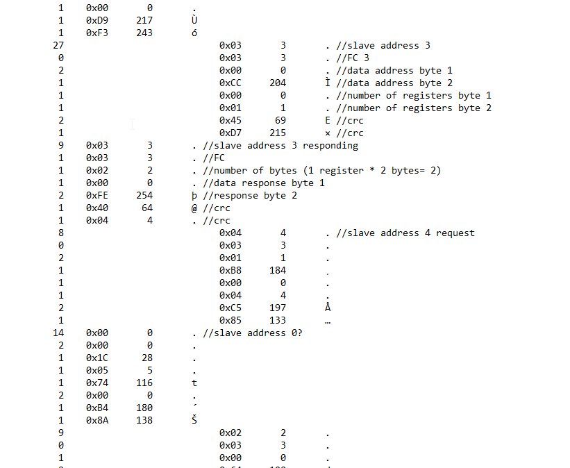
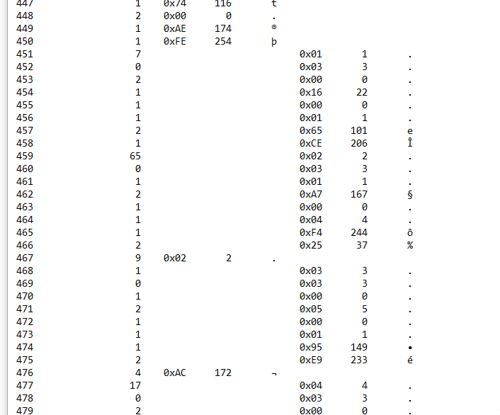
I am working with drager gas detectors there are 5 LEL in a dasiy chain loop. I am able to read values in anybus for 3 of them (any 3). As soon as I add 4th in the loop. Data stops. We have 8 parameters against each device so 24 as of now which is within the max limit. Not sure what’s causing we checked all combination. Not sure why its happening. I am assuming if I am able to read data from 3 that means anybus configuration is good. Below are some details -

  1. Field bus type EthernetIP - Modbus TCP 2 port
  2. Baud rate 9600
  3. Parity even
  4. Update mode -cyclically
    Anybus - 7072
    Distance between the anybus and LELs should be less than 800 feet. All LEL are in same room at a distance of 5-10 feet from each other.

LEL-CAB04 - 10.201.8.64 1 3 and 5.cfx (7.0 KB)
LEL-CAB04 - 10.201.8.64 Part1full.cfg (16.0 KB)
LEL-CAB04 - 10.201.8.64 1 3 and 5.cfg (16.0 KB)
LEL-CAB04 - 10.201.8.64 Part1full.cfx (13.7 KB)

Hello @Swaraj,

I don’t see any issues with the configuration. My guess is something is happening on the bus. Does the 3 device config work even with all the devices connected? Do you have proper RS485 termination and biasing? We have a diagram on page 129 of the User guide.

Do you still see both TX and RX traffic in the log? Can you provide a log with both configurations running?

Deryck

Hi Deryck,

I am attaching the log file

log with 4 devices 1,2,3 and 5.txt (31.7 KB)

Does the 3 device config work even with all the devices connected?
-Once I add other device on anybus it sends data intermittently. Not sure why this happens.

Do you have proper RS485 termination and biasing? We have a diagram on page 129 of the User guide.

  • Yeah they are terminated correctly.

Do you still see both TX and RX traffic in the log? Can you provide a log with both configurations running?
I have attached one with 4 devices in loop. You can see intermittent data.

Kind Regards
Swaraj

Hi Deryck,

I had sent the information yesterday, seems like it didn’t get through, so writing it again

Does the 3 device config work even with all the devices connected?

  • As soon as 4th device is configured in anybus the data stops and its intermittent, that is the data is received after waiting for 2-3 minutes, only one point at at time.

Do you have proper RS485 termination and biasing?
-Yes its terminated properly we have 5 loops working with more than 4 devices in each loop.

Do you still see both TX and RX traffic in the log? Can you provide a log with both configurations running?
I have configured all points for read. I am attaching the log file for information

log with 4 devices 1,2,3 and 5.txt (31.7 KB)

Hello @Swaraj,

We received both all posts reviewed before they are approved to be posted. We typically have the staff member assigned to the topic approve posts. In this case I didn’t get a change this morning to look at and approve them.

Looking at the log it seems like you might have devices causing uncalled for data on the bus. It seems like some responses go fine but, from what I can tell, something else is dumping data on the bus. the screen shot below with some comments added shows a successful message to node 3 but the query sent to node 4 gets an invalid response that i can not match us with any modbus response.

As i look further down the log there are more received messages that are not valid.

This seems to indicate there is an issue on the serial bus but it is hard to say exactly what. Are you sure all the devices are configured with the same serial settings? Do they all have unique node/slave ID’s?

Deryck

Hi Deryck,

Thanks for the information, its helpful. However, we tried each sensor getting integrated one by one on this anybus and they all worked. We even tried multiple combination of 3 devices like 1-2-3, 2-3-4, 3-4-5, 1-3-5, 1-2-4, 1-4-5 and 1-2-5 and they all work. As soon as 4th in the loop hops in it messes the whole thing. We are speculating that it might be the distance like 800 feet might be much for the loop. I don’t know what else to look for we checked all nodes they are unique and configured the way I have configured in anybus plus modbus communication is also configured the way I did it in anybus.
I will keep you posted about what’s the result is with respect to reduction of distance. We will be doing it in 2-3 days from today.

Kind Regards
Swaraj Ostwal

Thanks for the follow up. You might also be able to reduce the baud rate over shortening the bus.

Deryck

Hi Deryck,

Unfortunately the drager sensor can’t go below 9600 so reducing the distance is the only option.

Kind Regards
Swaraj

Hi Deryck,

So, seems like distance was the issue. We got the panel shifted closer to the sensors and and all 5 worked. Sensor and anybus communication had no change in their configuration.

Kind Regards
Swaraj Ostwal

Hi Swaraj,

Thanks for following up. Good to hear the issue was resolved with distance. Perhaps it was a reflection issue due to the length.

Deryck

Hi Deryck,

After resolving the issue, for better understanding purpose and designing the system I would like to know the following things -

  1. With baud rate 9600 how’w the distance calculated for the loop in RS 485. For example if A is my Anybus gateway and B, C, D, E, F and G are my 6 modbus RTU devices. Then Loop distance is A-B-C-D-E-F-G-A (if they are wired like A to B to C to D to E to F to G) Or will it be (A-B) + (A-C) + (A-D) + (A-E) + (A-F) + (A-G).
    The reason why I ask is A to G (last in loop) was not more than 800 feet but we only had 3 communicating. As per documentation modbus RTU could go upto 4000 feet with a repeater.

  2. Is there any document from HMS that describes how may devices can work in a specific distance at various baud rate.

I am sorry for asking some basic question here, but way the things are working and what documentation says looks different to me. Getting answer to this question will help me workout better with anybus since we are getting more anybus gateways and with this information I can have correct placement of panel holding these anybus. This will help us for better installation and design rather than learning the hard way.

Kind Regards
Swaraj Ostwal

Hello,

RS 485 is for a bus layout so the distance would be from the first device to the Last. A to G in your example. If the device was dropping off you might have resistance in the line, noise, or reflections happening. It is also worth mentioning that the 4000ft length is limited to 100kbps.

Im not aware of any documentation from HMS on the baudrate and distance. I did find this document from TI when looking for info on the rs485 spec. http://www.ti.com/lit/an/slla272c/slla272c.pdf They have a section on distance to bitrate. its not very straight forward to go from bitrate to baud rate but this calculator seem to get close enough. https://www.calculator.org/properties/data_rate.html

The Wikipedia page on rs485 also provide some useful info. https://en.wikipedia.org/wiki/RS-485

Hi Deryck,

Thanks for the info, I was checking the speed Kbps and baud rate relation. 9600 baud rate is close to 8Kbps, basically 960 bytes per sec hence close to 8Kbps. As per documentation 1000 feet work fine for speed less than 90Kbps. However one unknow in this entire conversation is resistance in the loop which might the one that creates the problem as well as noise which could also affect this. Anyways thanks for the information, I will look into these documents and update if I have any findings.

Thanks for the support
Swaraj

1 Like