GSD, ADI List, PROFIBUS Sim, Getting started

Hi,

Trying to get started with using the PROFIBUS Simulator to get started with a GSD file and a few ADI mappings in my code.

This seems to work ok:

const AD_AdiEntryType APPL_asAdiEntryList[] =
{
/* 1/0 */   { 256,   "PipeDiam",        ABP_FLOAT,   1, APPL_READ_MAP_WRITE_ACCESS_DESC, { { &g_stConfig.Alg.fPipeDiam, NULL } }, NULL, NULL}, 
};

const AD_MapType APPL_asAdObjDefaultMap[] =
{
   { 256, PD_READ,  AD_MAP_ALL_ELEM, 0 },
   { AD_MAP_END_ENTRY }
};

with this I can use the simulator DPV2 master acyclic interface to perform reads and writes on &g_stConfig.Alg.fPipeDiam

I can also use the GSD file with the following Module define to modify &g_stConfig.Alg.fPipeDiam with the Simulators ‘Start with GSD’ function

Module = "PipeDiam" 0x83,0xC1,0x00,0x00,0x01;
1
EndModule
;

The problem starts when I try to add a second index to the slot:

const AD_AdiEntryType APPL_asAdiEntryList[] =
{
/* 1/0 */   { 256,   "PipeDiam",        ABP_FLOAT,   1, APPL_READ_MAP_WRITE_ACCESS_DESC, { { &g_stConfig.Alg.fPipeDiam ,NULL } }, NULL , NULL },  
/* 1/1 */   { 257,   "Viscosity",       ABP_FLOAT,   1,     APPL_READ_MAP_WRITE_ACCESS_DESC, { { &g_stConfig.Usr.fViscosity ,NULL  } }, NULL , NULL },
    };

const AD_MapType APPL_asAdObjDefaultMap[] =
{
   { 256, PD_READ,  AD_MAP_ALL_ELEM, 0 },
   { 257, PD_READ,  AD_MAP_ALL_ELEM, 0 },
   { AD_MAP_END_ENTRY }
};

(I can use the acyclic read/write successfully here for both of these)

But the GSD file below gives a ‘cfg fault’:

Module = "PipeDiam" 0x83,0x41,0x00,0x00,0x01;
1
EndModule
;
Module = "Viscosity" 0x83,0x41,0x00,0x01,0x01;
2
EndModule
;

image

I feel like I’m just missing something basic here. Trying to crawl before I run, ya know…
Anyone see what I’m missing?

Thanks,
-ed

I did discover one error in my GSD Module definition.
The length byte is 0 = 1, so the correct definitions should be:

Module = “PipeDiam” 0x83,0xC0,0x00,0x00,0x01;
1
EndModule
;
Module = “Viscosity” 0x83,0xC0,0x00,0x01,0x01;
2
EndModule
;

Unfortunately this still results in the ’ Wrong Submodule’ error in the simulator.
I’m wondering now if I’m not using the simulator properly.
Here’s what I’m doing.

File> Open GSD…
Selecting and Inserting ‘PipeDiam’, then hitting OK
image

Then Communication > Open with GSD

I then see the same result as above (Cfg Fault, and wrong submodule errors on both slots)

I’ve been referencing this post, and it seems very similar to my implementation. Not sure why mine would not work.

-ed

I also attempted changing to bytes instead of words as the count…
Module = “PipeDiam” 0x83,0x83,0x00,0x00,0x01;
1
EndModule
;
Module = “Viscosity” 0x83,0x83,0x00,0x01,0x01;
2
EndModule
;

and the sim shows this

a little different in the left window, which seems odd. I would have expected four lines on both the first screen cap and this one if the data size was four bytes/ one word…

Hi Ed,

I am thinking you have something set incorrectly in the GSD. My guess might be that the last part, the vendor specific data might not have the correct ADI values set which is causing the wrong sub module error.

see the examples in section D hms-hmsi-27-210.pdf (hms-networks.com)

Deryck,

From what I see those bytes define the ADI number. Mine is 256 (0x100), so my last two bytes in the Module definition are

Module = “PipeDiam” 0x83,0x83,0x00,0x00,0x01;

where the example of 300 (0x12C) is
Module = “ADI 300” 0x43,0x81,0x00,0x2C,0x01;

so that seems correct to me

-ed

I should add that it works fine if I only have a single module entry of 256 (Slot 1 index 0). the problem comes up when I add a second module/ADI of 257 (Slot 1 index 1). The example is for one read and one write.

Hi Ed,

Sorry you are correct i quickly looked at your example wrong. I went though and your ADI entries look correct in your EDS. Could you share you entire eds file for me to check over perhaps we are over looking something.

I am checking with some colleagues to see if they have any additional input.

Deryck

HMS_edtest.gsd (16.2 KB)

Here you go!
-ed

Something I noticed later - if I don’t select a parameter and just load ‘Global’ it appears things work:

image

Although I’m getting constant writes to those two variables!

-ed

Thanks Ed,

I am still waiting for some feedback from my colleagues more versed in profibus. I am also looking into your questions regarding the master simulator.

I am thinking this might have something to do with how you are setting up the connections but I am not sure what. I hope to update you tomorrow or monday. (my colleagues are on holiday)

Deryck

Thanks for passing it forward. I’m new to the inner-workings of Profibus as well, so I appreciate the assistance.
-ed

Hi Ed,

I believe I have most of this sorted out. The errors and issues might come down to how you have the data mapped in the ABCC. Along with how the master simulator is establishing the connection. Using the easy start in the Master simulator the Master is getting the default mapping from the module then starting the connection. When you go online using the GSD file is is trying to create a connection according to how you tell it to. I am guessing that you don’t have ABCC_CFG_REMAP_SUPPORT_ENABLED set True. So only your default mapping is used by the compactcom. This is most likely what is happening automatically when no modules are added to the configuration.

If you mapped the parameters to match your default mapping then you should see the same connection setup. If your default mapping is still set as you have posted in your first request this mapping should work:
image

Notice how the config is different depending on how you make the connection?


VS

In some sense you can check your GSD file using the quick start since it uploads it from the compactcom.

Enabling Remap would allow the compactcom to remap the ADI’s at run time. This might not have the desired effect since parameters you don’t need or want mapped for cyclic can be.

Hi Deryck,

Ah! That was huge!

Enabling REMAP was it.

(I added a bunch more parameters, read and write, below)

I think I understand the difference between the two interfaces now.

When I load a single module, there isn’t a cyclic connection, so the ‘Start with GSD’ does not ‘connect’ now, but acyclic read/writes should be done with the DVP1 dialog instead.

(I don’t think I’m suppose to be able to do reads/writes this way)

As long as when I get to creating the FDI/EDD for Profibus I can do both the cyclic and acyclic reads and writes, I should be good.

I do see that once I ‘Start with GSD’ with a single module, I get a debug message from the CCom:

“New process data sizes RdPd 4 WrPd 20”

And I need to restart to be able to get the cyclic connection to work again.

Not sure that I understand that yet.

Thanks so much!

-ed

I’m not sure this understanding is accurate. The default map is what the compactcom has setup for a map. with your map being:
const AD_MapType APPL_asAdObjDefaultMap[] =
{
{ 256, PD_READ, AD_MAP_ALL_ELEM, 0 },
{ 257, PD_READ, AD_MAP_ALL_ELEM, 0 },
{ AD_MAP_END_ENTRY }
};
The expected connection is for adi 256 and 257. When you just add one you are getting an error response since the connection the master is asking for does not match the one on the module. The error message is actually pulled from the EDS which in my opinion is an inaccurate message. “wrong submodule” might make more sense to just say wrong slot or mapping.

enabling remapping may or may not be the best option here. remapping allow the compactcom to remap the ADI based on the configuration the master ask for but it might make more sense to just have a mapping setup for all the data that is needed to run the module. Then the master just needs to setup the connection to match.

Deryck

Hi Deryck,

I’ll admit, now I’m completely lost.

If I can, let me reset the conversation to see if that helps.

I’ll explain what I’m trying to accomplish first.

In my device I have three types of parameters…

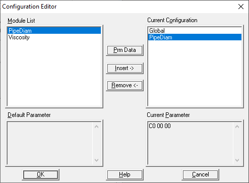
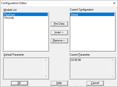
  • Configuration settings that are read once and write once (as I understand ‘acyclic’) (slot 1)
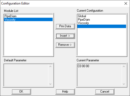
  • Results or ‘inputs’ which are read constantly by the master (‘cyclic’) (slot 2)
  • ‘Outputs’ which are written constantly to my device (also ‘cyclic’) (slot 3)

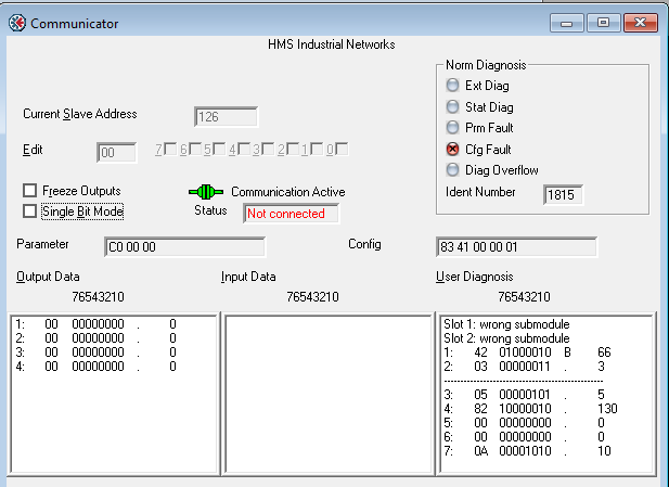
With what I have the configuration settings are being written to constantly (not what I need) and I don’t understand why that is.

Below is my current code, I’ve attached the GSD I’m using.

const AD_AdiEntryType APPL_asAdiEntryList[] =

{

/* S/I */

/* 1/0 */ { 256, "PipeDiam", ABP_FLOAT, 1, APPL_READ_MAP_WRITE_ACCESS_DESC, { { &g_stConfig.Alg.fPipeDiam ,&appl_sFloatProp[FP_PipeDiam] } }, GetAdiValue, SetAdiPipeDiamValue },

/* 1/1 */ { 257, "Viscosity", ABP_FLOAT, 1, APPL_READ_MAP_WRITE_ACCESS_DESC, { { &g_stConfig.Usr.fViscosity ,&appl_sFloatProp[FP_Viscosity] } }, GetAdiValue, SetAdiValue},

/* 1/2 */ { 258, "ReynoldsC0", ABP_FLOAT, 1, APPL_READ_MAP_WRITE_ACCESS_DESC, { { &g_stConfig.Usr.fReynoldsC0 ,&appl_sFloatProp[FP_NORange] } }, GetAdiValue, SetAdiValue},

/* 1/3 */ { 259, "ReynoldsC1", ABP_FLOAT, 1, APPL_READ_MAP_WRITE_ACCESS_DESC, { { &g_stConfig.Usr.fReynoldsC1 ,&appl_sFloatProp[FP_NORange] } }, GetAdiValue, SetAdiValue},

/* 1/4 */ { 260, "ReynoldsC2", ABP_FLOAT, 1, APPL_READ_MAP_WRITE_ACCESS_DESC, { { &g_stConfig.Usr.fReynoldsC2 ,&appl_sFloatProp[FP_NORange] } }, GetAdiValue, SetAdiValue},

/* 1/5 */ { 261, "VolUnits", ABP_UINT8, 1, APPL_READ_MAP_WRITE_ACCESS_DESC, { { &g_stMapConfig.ucVolUnits ,&appl_sUCProp[UC_VolUnits] } }, GetAdiMapValue, SetAdiMapValue},

/* 2/0 */ { 511, "VFFiltered", ABP_FLOAT, 1, APPL_WRITE_MAP_READ_ACCESS_DESC, { { &g_stDSPDiagnostics.fVFFiltered ,NULL } }, GetAdiValue, NULL },

/* 2/1 */ { 512, "SOSFiltered", ABP_FLOAT, 1, APPL_WRITE_MAP_READ_ACCESS_DESC, { { &g_stDSPDiagnostics.fSOSFiltered ,NULL } }, GetAdiValue, NULL },

/* 2/2 */ { 513, "GVFFiltered", ABP_FLOAT, 1, APPL_WRITE_MAP_READ_ACCESS_DESC, { { &g_stDSPDiagnostics.fGVFFiltered ,NULL } }, GetAdiValue, NULL },

/* 2/3 */ { 514, "VFQuality", ABP_FLOAT, 1, APPL_WRITE_MAP_READ_ACCESS_DESC, { { &g_stDSPDiagnostics.fVFQuality ,NULL } }, GetAdiValue, NULL },

/* 2/4 */ { 515, "SOSQuality", ABP_FLOAT, 1, APPL_WRITE_MAP_READ_ACCESS_DESC, { { &g_stDSPDiagnostics.fSOSQuality ,NULL } }, GetAdiValue, NULL },

/* 3/0 */ { 766, "Pressure", ABP_FLOAT, 1, APPL_READ_MAP_WRITE_ACCESS_DESC, { { &g_stExternalInputs.fPressure ,&appl_sFloatProp[FP_NORange] } }, GetAdiValue, SetAdiInputValue },

/* 3/1 */ { 767, "Temperature", ABP_FLOAT, 1, APPL_READ_MAP_WRITE_ACCESS_DESC, { { &g_stExternalInputs.fTemperature ,&appl_sFloatProp[FP_NORange] } }, GetAdiValue, SetAdiInputValue },

};

/

const AD_MapType APPL_asAdObjDefaultMap[] =

{

{ 256, PD_READ, AD_MAP_ALL_ELEM, 0 },

{ 257, PD_READ, AD_MAP_ALL_ELEM, 0 },

{ 258, PD_READ, AD_MAP_ALL_ELEM, 0 },

{ 259, PD_READ, AD_MAP_ALL_ELEM, 0 },

{ 260, PD_READ, AD_MAP_ALL_ELEM, 0 },

{ 261, PD_READ, AD_MAP_ALL_ELEM, 0 },

{ 511, PD_WRITE, AD_MAP_ALL_ELEM, 0 },

{ 512, PD_WRITE, AD_MAP_ALL_ELEM, 0 },

{ 513, PD_WRITE, AD_MAP_ALL_ELEM, 0 },

{ 514, PD_WRITE, AD_MAP_ALL_ELEM, 0 },

{ 515, PD_WRITE, AD_MAP_ALL_ELEM, 0 },

{ 766, PD_READ, AD_MAP_ALL_ELEM, 0 },

{ 767, PD_READ, AD_MAP_ALL_ELEM, 0 },

{ AD_MAP_END_ENTRY }

};

Changing the ABCC_CFG_REMAP_SUPPORT_ENABLED flag does not appear to change anything

The GSD only lists slots 2 and 3

-ed

CIDRA_.gsd (16.8 KB)

It appears that if I just leave out the ADIs I don’t want as cyclic from the APPL_asAdObjDefaultMap it works as I think it should.

I have read/write access to the config settings via the DPV1 interface, and the inputs update through the GSD interface.

What I missed all along was that the APPL_asAdObjDefaultMap needed to include ALL the ADIs in APPL_asAdiEntryList.

-ed

Hi Ed,

Sorry about I haven’t had a chance to follow up. I was trying to find you something that would give more details on this. But, yes the default mapping is setting the ADI’s up for Cyclic data. If they are not mapped the ADI’s are still available just not mapped for process data.

Deryck

Hi Deryck,

That’s ok on not getting back right away – I was pretty lost! :wink:

May I ask if there is a limit to the size of the “APPL_asAdiEntryList”?

Thanks,

-ed

There really isn’t a limit to the Entry list but there are network limits you would want to keep in mind.
This table should give you a better idea of the limits.

image

I recommend looking at the fill table in the Software design guide.
hms-hmsi-216-125.pdf (hms-networks.com)