Having trouble setting up AB9006 with Schneider M262

My customer is having the same exact issue with a M 262 Schneider PLC.
It is not clear from the Anybus documentation, how to set up the AB9006 for anything other than an Allen Bradley PLC.

The EDS file does not seem to work out-of-the-box for other PLC systems.
Does the EDS file and/or any configuration need to be customized depending on how one sets up the EthernetIP-Modbus mapping/transactions?
Or is the EDS file supposed to be generic for the Anybus device?

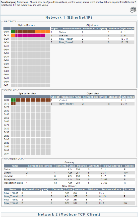
How do I go about translating what I see on the “Mapping Overview” to the settings I need to configure on the M262 PLC to get the EthernetIP configurations to match between the Anybus and the PLC?
This is basically the same question that @tbuechler is asking.

It should work with any Ethernet/IP Scanner (master).

No, the EDS file does not need to be changed. The Modbus transactions you create will create the IO space that is read from the Eth/IP scanner. For example, if you create a read holding registers transaction for 10 registers, that will create 20 bytes of input data on the Ethernet/IP network. You can view this IO area in the ‘Data Mapping Overview’:

You will add the Anybus to your Ethernet/IP network, either by using the EDS file or manually setting the connection points with the correct input and output sizes:

Input 100 size (depends on config)
Output 150 (depends on config)
Config 1 size 0

You will add the Anybus to your Ethernet/IP network, either by using the EDS file or manually setting the connection points with the correct input and output sizes

Ok, so to clarify, the EDS file is such that it works no matter how I configure the Modbus transactions, in other words the Ethernet/IP scanner is able to automatically understand the input and output sizes when it connects to the Anybus Ethernet/IP side?

No, the Input and Output sizes must also match in the Scanner, or the Ethernet/IP connection will fail.

Ok. So the EDS file is just a starting point. But after loading it, I still need to go and change the Input and Output sizes of the “Anybus device” (from my ethernet scanner, i.e. PLC program) based on the specific “Mapping” that I have created.

Correct me if I’m wrong - for the example screenshot you posted, the input size would be 29 bytes and the output size would be 17 bytes? Is that how I’m supposed to read it?

It would actually be 30 bytes and 18 bytes in this case, since the addresses start at byte 0. Other than that you are correct, you can look at the mapping page to see the data sizes coming in and going out.

Roger that. Thank you @hugh_hms and @kyle_HMS !