Hello,
I am using a siemens S7 1200 PLC with the CM can open module as a master CAN Open manager.
I have two slave devices in the form of a 8400 Stateline C safety lenze drive and a 8400 Topline C safety lenze servo drive.
Module is node ID 127 stateline is 101 and topline is 102.
I am trying to send 32 bytes of data and receive 32 bytes of data via the process image.
Initially i was unable to get my can module out of a heartbeat/nodeguarding error(double led flash on err light)
I then tried to set the modules hardware config to auto configuration (tia portal 16). This solved my problem and the communications then started to work which was great.
However i then noticed that for the second node 102 I was missing some data and the data i was receiving was in an unexpected location.
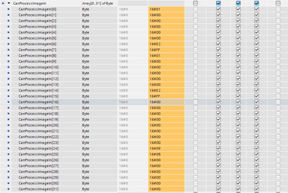
In my plc i have a process image in data area that is an array of 0…31 bytes.
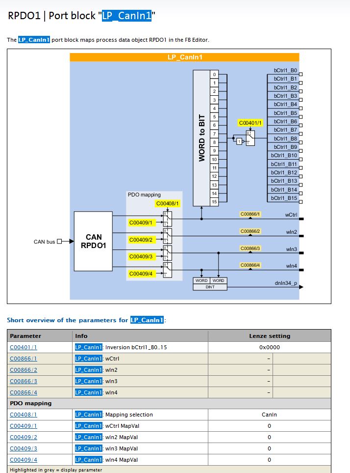
from the drives i am sending 2 can open ports named LP_Canout1 and LP_Canout2 both of these represent 4 words of data each so 16 bytes from the drive.
I am receiving this fine from drive node 101 and it can be see in my array on bytes 0…15 no problem.
However the next 8 bytes which i would expect to have the first 4 words from LP_Canout1 are blank with no data and are instead mapped to bytes 24…31 and i am missing the data from LP_Canout2 from drive node 102.
Drive node 101 (Working OK)
LP_Canout1 : 4 words or 8 bytes mapped through to PLC on bytes 0…7
LP_Canout2 : 4 words or 8 bytes mapped through to PLC on bytes 8…15
Drive node 102
LP_Canout1 : 4 words or 8 bytes mapped through to PLC on bytes 16…23 (No data on here)
LP_Canout2 : 4 words or 8 bytes mapped through to PLC on bytes 24…31 (Data from LP_Canout1)
The LP_Canout1/2 ae function blocks used in the lenze drives that are inserted into an FB editor so you can map data to them there. I hope i have explained all this with some level of clarity.
I suspect the module may be using some default PDO setting when i set it to autoconfigure and maybe this is causing me the problem but them I am not sure why it is ok for the first drive and not the second drive. I am quite new to all this can open stuff so its all still a bit confusing. Any light that can be shed would be greatly appreciated.