Hello,
Another question
How can i write an NMT telegram from TIA portal?
AS slave SDO’s are read only in Pre-Operational, and on startup it switches to Operational automatically.
Can any one please give an example how to do that?

Hello,
Another question
How can i write an NMT telegram from TIA portal?
AS slave SDO’s are read only in Pre-Operational, and on startup it switches to Operational automatically.
Can any one please give an example how to do that?
are writable in Pre-Operational
*edit
CM CANopen: NMT telegrams
must be differentiated between
a) CM CANopen is running as a CANopen Slave
CM CANopen is only allowed to send the NMT command: set all nodes to operational
condition:
1. there must not be a CANopen master connected to the CANopen network
2. CM CANopen must be configured as a self-starting device
=> configuration of 1F80h,subindex 0: 0x0000000A
b) CM CANopen is running as CANopen Manager
note: set a device to operational
=> a slave device can be only set to operational
1. when it is configured as slave
=> CM CANopen Configuration Studio
Bit 0 of its NMT Slave must be set
2. when it has must be set been booted successfully
=> see chapter 8.1.4 Get Node & Network Status of the manual of the CM CANopen
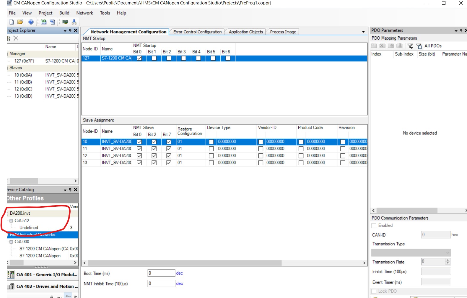
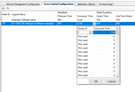
hint: CM CANopen Configuration Studio: Network Management Configuration
a) NMT Startup
Bit 2 should not be set
=> CM CANopen will automatically set itself to operational at the end of the network initialization
Bit 3 should not be set
=> CM CANopen will automatically set successfully booted slaves to operational
b) Slave Assignment
Bit 0 must be set
=> otherwise a present device is managed as a failure
Bit 2 should be set
=> otherwise a failed boot slave process will not be repeated automatically
NMT telegrams are requested by SDO write command:
addressed device:
CANopen node id of the CM CANopen
index: 1F82h (Request NMT)
subindex: value range: 1 … 127 decimal
CANopen node id of the device that shall execute the requested NMT command
value: 128 decimal
all nodes including the CM CANopen
data of index 1F82h, subindex 1 … 128
data size: 1 Byte
values:
04h: enter Stop
05h: enter Operational
06h: execute Reset node
07h: execute Reset communication
7Fh: enter Pre-Operational
Example:
CM CANopen uses the CANopen node id 127
slave device with CANopen node id 1 shall be set to operational
Note:
WriteSDO FB is different form the description in the manual: it is based on a revised library (I have attached the revised library)
// initialize data to be sent
// 16#1F82, subindex x:
// => byte size: 1 byte
// => value:
// 04h: enter Stop
// 05h: enter Operational
// 06h: execute Reset node
// 07h: execute Reset communication
// 7Fh: enter Pre-Operational
//
// note: DATA
// data type: “SDO_WriteData”
// “SDO_WriteData”: Array[1…x] of Byte x: can be set by the customer
//
// example
// “DB_SDOWrite_Data”.Data: DB that holds the data to be written
// data type: “SDO_WriteData”
//
// note: data format of the value <=> little endian <=> LSB first MSB last
// LSB of the value: “DB_SDOWrite_Data”.Data.SDO_WriteData[1]
//
“DB_SDOWrite_Data”.Data.SDO_WriteData[1] := 5; // example: set operational
“WriteSDO_DB”(REQ:=TRUE,
ID:=“Local~CM_CANopen_1”, // hardware identifier of the acessed CM CANopen in TIA Portal
SLOT:=16#0, // used SDO channel of the CM CANopen
NODE:=127, // CANopen node id of the CM CANopen: here 127
INDEX:=16#1F82,
SUB:=16#1, // CANopen node id of the device that shall execute the NMT command: example: 1
DATA:=“DB_SDOWrite_Data”.Data,
DATASIZE:=1, // byte size of 1F82h, subindex x: 1 byte
BUSY=>#fBusy,
RET=>#uiRet);
IF #fBusy = TRUE THEN
// command is running
;
ELSE
// command has been processed
// #uiRet informs about the result
;
END_IF;
Great! Thanks for the update!
Hi!
Really helpful information but I still can’t understand.
For example:
I need to control few INVT Servodrives (to servomotors) through CANopen module and PLC S7-1200.
Have I choose operating mode: CANopen as a slave?
Or like CANopen as a manager?
P.S.: I have EDS-file for INVT servodrive and configuration index which I have to use for control servodrives.
Regards, Alex.
In this case, you will likely want to configure the CANopen module as the manager. Please see:
Use the CM CANopen Configuration Studio from the product page.
Hello, sir!
Thank you for your previous reply.
I have read the manual and downloaded the CM Configuration studio… I watched a demo video on YouTube several times on configuring the canopen module in TIA Portal. When configuring the module in the tia portal, I select node-id 127 and the canopen as manager or slave mode(no matter as a result). Load it into the PLC.
In CM Configuration Studio I added a master device and slaves. In the Application object, I mark the necessary node index for working in TIA Portal. Generate then dowmload to device(PLC - CPU 1217C DC/DC/DC). The download is successful. I connect to the PLC online, but I do not see the available tags, those nodes that I loaded into the CANOpen module. They are missing…
P.S. I use servo drives INVT DA200 act as nodes. eds file is added without warnings. CiA protocol 512.
What have I missed?
Best Regards,
Alex
CiA 512? Are you sure about that?
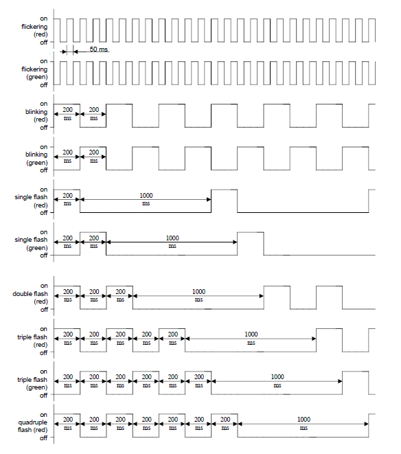
It is very important that we know the status of the RUN and ERR LED of the CM CANopen. (See below for blink patterns.) They inform us if there is CAN communication, if the slave devices are present and have been configured successfully.
I was speaking with an associate here, Christian, who is an expert with CANopen, about your case and he sent me the following information. We need to make sure we have a stable communication between the CM CANopen and the slave device before we can proceed so it’s very important to let us know the status of the LED light on the CM CANopen.
Hint:
do not run any commands from the PLC to the CM CANopen until the configuration of the network is successful
the only exception is the processing of the “Get node & Network Status” command which provides the necessary information to analyze the network
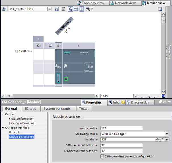
The very basic configuration of the CM CANopen is done by the device configuration in TIA Portal.
The CM CANopen must run as CANopen Manager
Note:
CANopen Manager auto configuration must not be activated
Node number must be identical with Node-Id of “Manager” in the Configuration Studio
CAN baudrate must be identical for all connected CANopen devices
CANopen input data size / CANopen output data size is not relevant until the slave device(s) have been booted successfully
=> ERR LED of the CM CANopen does not double flash
Example:
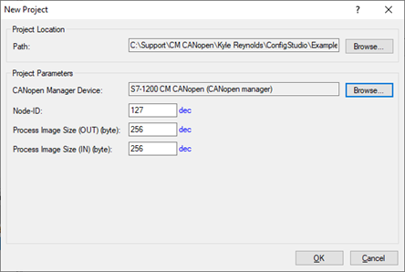
Note: Process image Size (OUT) (byte) / Process image Size (IN) (byte)
these parameters limit the maximum size of the process image in the Configuration Studio
Do not change !
the actual size of process image data that are exchanged between the PLC and the CM CANopen
is limited by CANopen input data size / CANopen output data size
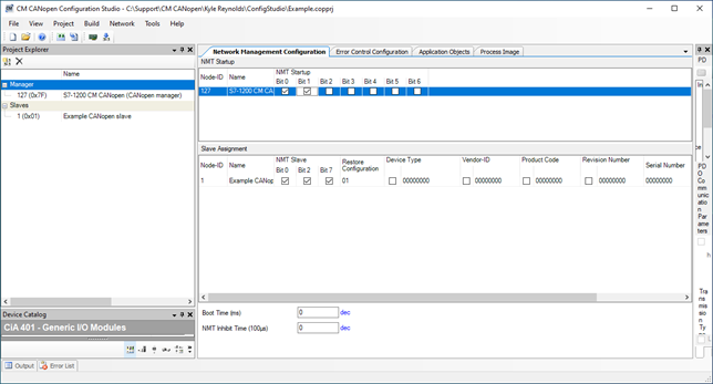
General hints:
NMT Startup
Slave Assignment
NMT Slave:
Boot Time (ms )
is not relevant for the CM CANopen
NMT Inhibit Time
if there are problems with the startup of the CANopen network set it to 100
Note:
some devices run in a receive queue overrun when there is a burst of NMT commands
example
Example:
see INVT SV_DA200 AC Servo Drive_CANopen Technical Guide.pdf
2.1 Basic settings for using CANopen
Before using CANopen on a common SV-DA200 servo drive, you need to set the following three parameters:
Set P0.03 (Control mode selection) to 7 (CANopenmode) through the LED panel or ServoPlorer software setting.
Set P4.02 (CAN communication baud rate) through the LED panel or ServoPlorer software setting
( 0 : 1Mbps; 1 : 500kbps; 2 : 250kbps; 3 : 125kbps; 4 : 50kbps; 5 : 20kbps).
Set P4.05 (CAN communication node) ó CANopen node id through the LED panel or ServoPlorer software setting (value range: 1–127).
RUN LED ON and ERR LED off
RUN LED is blinking and does not enter ON
ERR LED: single flash <–> no CAN communication
Reasons:
ERR LED: ON <–> bus off
Reasons:
RUN LED enters ON
Hello, Kyle!
I 've used all this setings before.
*LED status is - RUN LED is blinking and does not enter ON
*ERR LED of the CM CANopen does not double flash
*CAN baudrate for all connected CANopen devices is identical
*Node number identical with Node-Id of “Manager” in the Configuration Studio
*NMT Startup
*Bit 0 - set
*Bit 1 - set
*Slave Assignment
*NMT Slave:
*Bit 0 - set
*Bit 2 - set
*Bit 7 - set
*Basic settings for using CANopen INVT DA200 is correctly
Configuration was downloaded to CM CANopen module successfully.
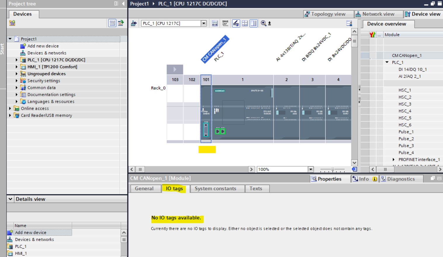
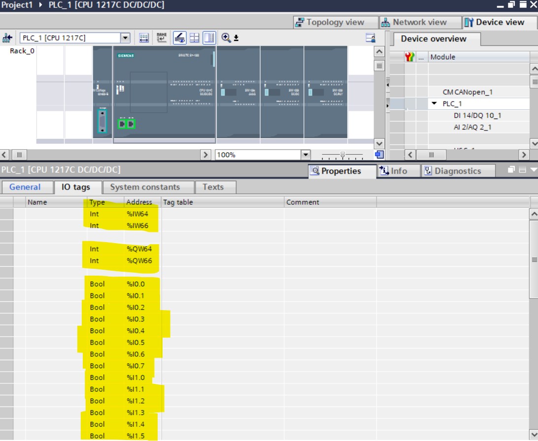
I can’t see any configured device’s addresses on TiaPortal like for example PLC’s addresses that I can use to bind tags to them
For example:
NO IO TAGS
Regards,
Alex.
What is the color and pattern?
Have you tried a lower baudrate?
GREEN LED - is blinking
Will try…
We have found that there is a bug in the CM CANopen where it can lose received CAN frames when the CAN baudrate is 500kBaud or higher.
This bug will be hopefully fixed before July.
I have just tried to change baudrate speed on CANopen and INVT Srevodrives from HIGH (1Mbit/s) to LOW (20kbit/s). Nothing changes. RUN LED is blinking, IOtags on TiaPortal is not available.
Also I have a question:
Have I use configuration file with function blocks for Tia Portal from https://www.ixxat.com/technical-support/resources/downloads-and-documentation?ordercode=021620-B
or it’s just nessesary for transparent CAN?
Regards,
Alex
This is from Christian who has been helping with this case:
I am wondering why the CM CANopen does not enter operational:
If the CM CANopen runs as CANopen Manager it should reach operational unless it’s alone on the bus. (not receiving any response)
this problem must be solved before we continue with the other ones
there are some possible reasons:
This situation can be caused when the devices start their CAN communication one after the other with a minimum delay so the CAN controller will reach warning level before the next CAN controller starts to communicate.
this event can be also caused by
a) the restore bit because restore forces a reset command of the CM CANopen (also specified by CANopen)
Slave Assignment
NMT Slave:
Bit 0 - set
Bit 2 - set
Bit 7 - set therefore: do not set Bit 7
b) a burst of NMT commands
the CM CANopen supports up to 16 parallel boot slave processes
each boot slave process starts with an individual NMT command
some devices are overwhelmed by a flood of NMT commands
therefore I suggest that in Configuration Studio / Network Management Configuration set:
- NMT Inhibit time (100µs) is set to minimum 100
please ask the customer if he can make a trace of the CAN bus traffic
note:
the CAN controller should not run in listen only mode
NO IO TAGS
The process image of the CM CANopen is not exchanged via the process image of the PLC.
The process image:
I have attached the CANopen demo that explains the relationship between the layout of the process image in the Configuration Studio and its transfer between the CM CANopen and the PLC.
This demo is created with TIA V13 and can be started with each later TIA version.
CANopen Demo.zip (7.0 MB)
I suggest that I have a teamviewer with the customer
- we need the TIA Portal
- the CM CANopen Configuration Studio
- and ( if available ): the possibility to display the CAN bus traffic
Do you have a USB-to-CAN device or some other way to see the raw traffic on the bus?
Can you try with bit 7 not set and let us know what happens?
Thank you for answer!
Bit 7 - is not set!
I’ve just looking through system contains tab CM CANopen module on TIA and found that port hardware identification is 272.
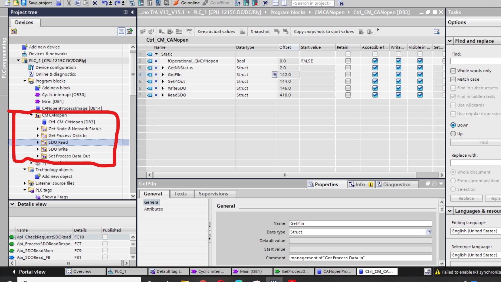
Also in EXAMPLE I found CANopen module program blocks.
Does it appear after configuring and loading the CM СANopen module into the TIA project? Or does this program block appear after adding a HSP file?
How can I get this program blocks?
Regards
Alex