Problems with HMS-EN2SE-R

Kyle,

Just to update and keep this thread alive, I had the supplier come on site once again, and demonstrate that they could read data from their device, even connected from the wiring at my end. However, using the same software and settings they used, I still read
garbage with my Laptop, and still get errors via the Anybus device. I am currently waiting the arrival of a different USB to RS485 converter to use with my laptop, so I can verify function at least to the terminal point in my equipment cabinet. There may
still be a question about the proper connections to the DB-9 connector on the Anybus device, but I’ll cross that bridge when I get to it.

Thanks,

Ross

Hi Ross,

Once you get a working USB-to-serial adapter, you should be able to use CAS Modbus scanner to do a “Discovery” and hopefully that will find these pesky registers.

Use “Device Manager” to confirm the COM port number for your USB-to-serial device.

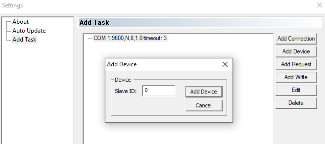
Add your connection and your device:

image

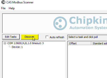
And just click “Discover.”

image

Hopefully this gives you an idea of which registers are readable.

Kyle

Kyle,

I apologize for the delay in response. This project got pushed to the back burner for a while. I am now resuming my diagnostics.
At last, I have been able to successfully read data from the originating device to my laptop, so I know that the serial configuration settings and the wire is good. At least, up to the junction where I inserted my laptop in place of the HMS module. There is still a short pigtail up to the 9-pin D-shell connector that could be in question. However, I have tested the wiring with an ohm meter, and confirmed that the 2 wires I am using connect to pins 8 and 9 of the connector.

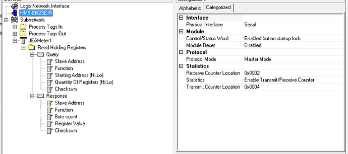
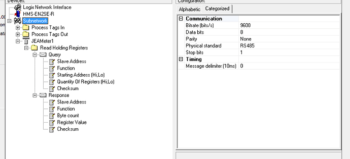
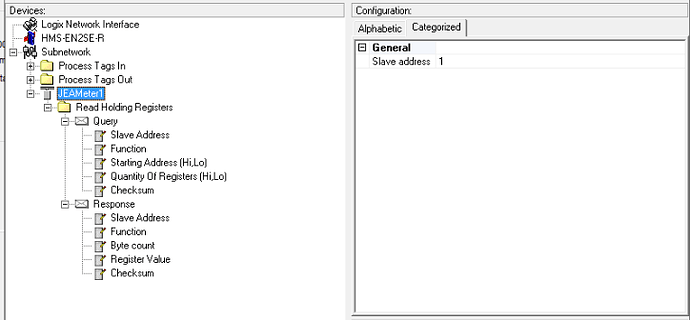
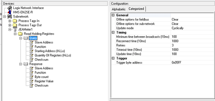
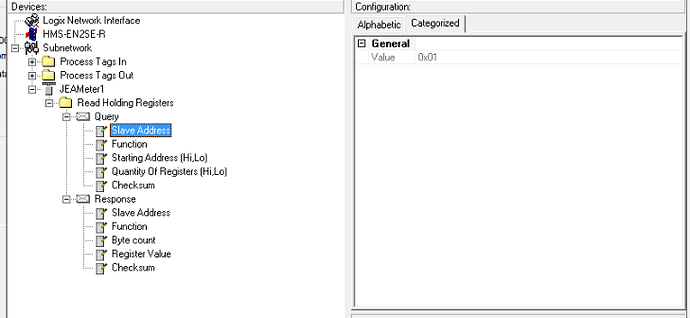
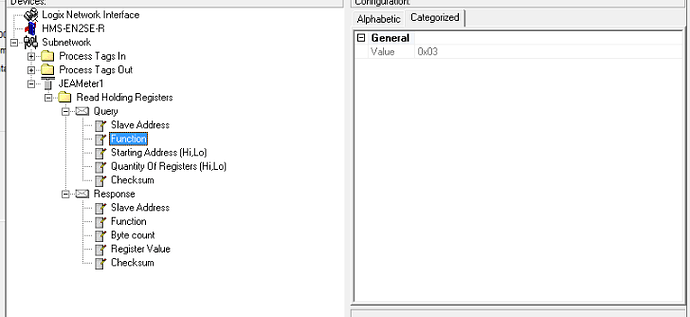
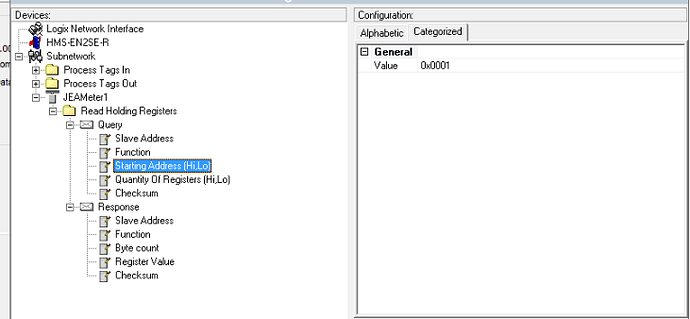
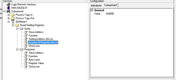
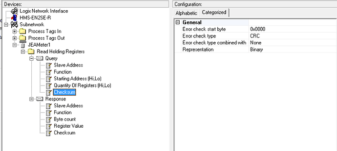
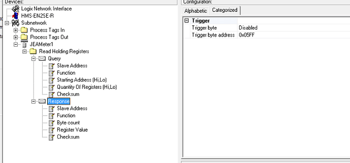
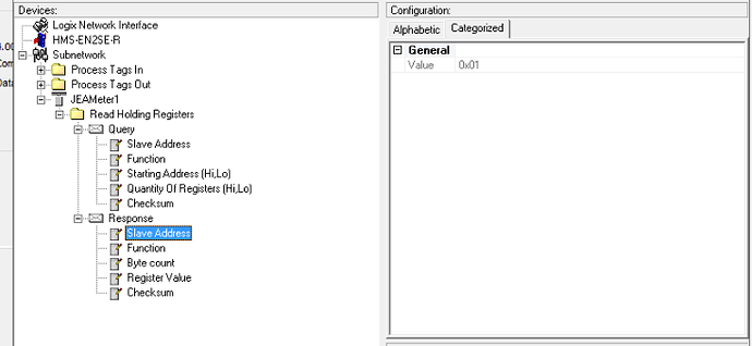
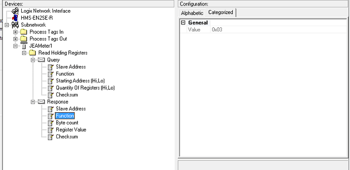
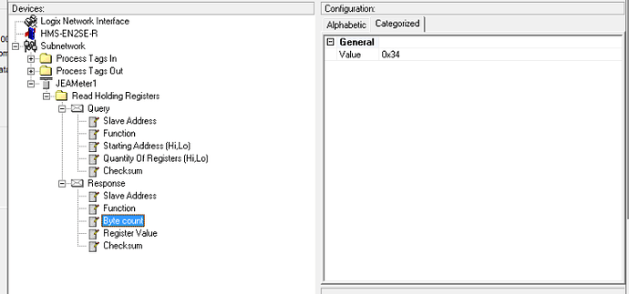
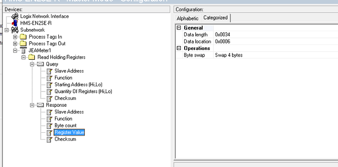
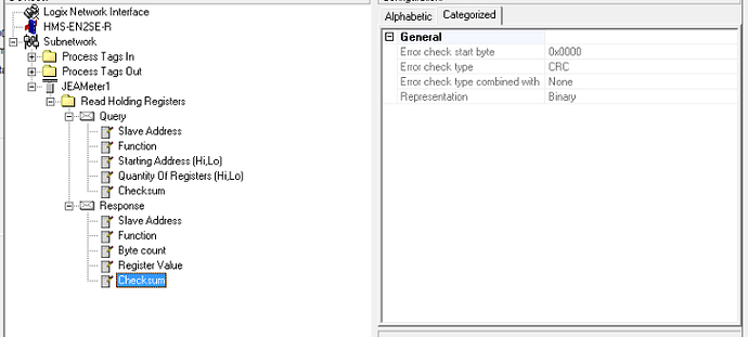
As of this moment, I have the module configured as shown:

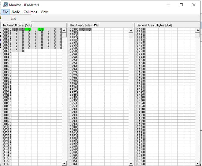
An the Node Monitor function returns these values:

image.png

I need to confirm that the Tx/Rx lines are not reversed, nut is there anything else that you suggest looking at?

Regards,

Kyle,

A bit more info -

The Red light called ‘5 - Subnet Status’ remains solid red, no matter which polarity is connected at pins 8 and 9 of the connector.

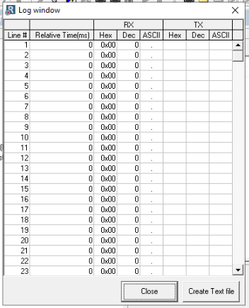
Attached is a short datalogger file. Hopefully, it means more to you than to me.

Also, there are no bias resistors at my end of the wire, but I believe they are enabled at the repeater that feeds me the signal. The registers read correctly when I attached the laptop to my end of the cable, so I assume that no resistors are needed, but I will certainly take that under advisement.

Regards,
Ross

image.png

log-07212020.txt (2.51 KB)

Hi Ross,

The log you made is showing no response from the node. Can you please send me a log of the data you are sending and receiving using the laptop so that I know how we need to mimic them using the Anybus?

Kyle

I’ll try to get that for you today, if the rain allows.

AS I mentioned, there is still the possibility that the short cable with the 9-pin D-shell connector is not correct. AS I read the manual, for RS485, 2-wire communication, the signals should be applied to pins 8 & 9 of the connector. Can you confirm that is correct?

Thanks,
Ross

Kyle, here are a couple of data files saved from the ‘Simply ModBUS’ diagnostic tool. I was never able to make the CAS ModBus Scanner tool function.

Also, I did find a bad connection in the short cable to the 9-pin connector, but even with that corrected, the Subnet Status LED remains solid red.

SimplModbusDatalog 2020-07-22 08.47.10.txt (519 Bytes)

Simply Modbus Master Byte History.txt (774 Bytes)

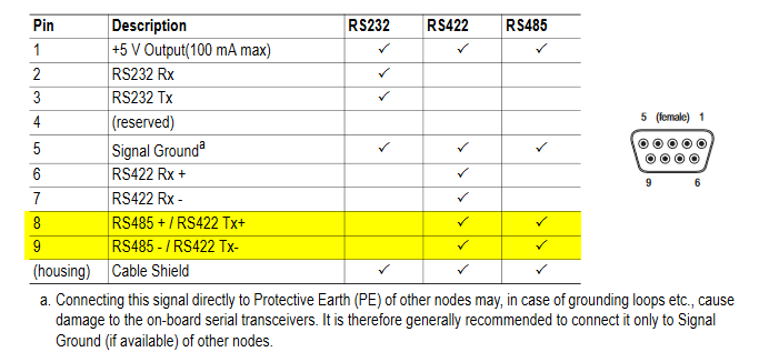
This is the pinout:

image

Can I ask, when you were using the Modbus simulator, how was your PC connected to the Modbus device. Did you use a Modbus to serial adapter? If so, what kind? Do you have a picture of it?

One thing I can see from the comparing the logs, the commands being sent by the Anybus are different than the ones you send with the Modbus simulator:

01 03 00 01 00 0D D5 CF Anybus
01 03 00 01 00 0E 95 CE Simlator

You should try sending the command exactly how it was sent with simulator.

That is the pinout I am working from, so hopefully it is all good now.

As for the commands, I am not certain I understand how to translate what you see from the ‘Simulator’ into transactions from the Anybus gateway. Apparently, using the standard ‘commands’ available in the Anybus configuration manager isn’t giving me what I need. It appears that using the ‘Transactions’ feature might allow more control of exactly what is communicated, yes?

This message may include restricted, legally privileged, and/or confidential information. If you received this message by mistake please delete it immediately and inform us about it. This message will be considered as originated from Gerdau or its subsidiaries only when formally confirmed by its officers authorized for that.

Este mensaje puede contener informaciones de uso restringido y/o legalmente protegido. Si usted ha recibido este mensaje por error, por favor eliminelo e informe de tal situación al remitente. Este mensaje solamente será considerado como proveniente de Gerdau o de sus subsidiarias cuando sea confirmado formalmente a través de los representantes legales debidamente autorizados para tal fin.

Kyle,

I am making some assumptions here (remember, I know nothing about ModBus).
According to these statements from your message below:

01 03 00 01 00 0D D5 CF Anybus
01 03 00 01 00 0E 95 CE Simlator

I assume that -

  • 01 is the node address
  • 03 is the ‘Read Holding Registers’ command
  • 00 01 is the Starting Address
  • 00 0D is the Quantity of Registers
    But beyond that, I am lost. What are the values DF CF (Anybus) and 95 CE (Simulator), and how do they relate? I don’t see any values in teh Anybus config that match, are they perhaps a CRC return value?

As for the USB to Modbus interface, I am using a Tripp Lite RS422-485 USB to Serial adapter cable, part #U209-30N-IND. It includes a 9-pin D-shell to screw-terminal adapter.

Thanks,
Ross

Sorry for the delay, I was out of the office on Friday. That is correct. The last two bytes are the checksum. You were also correct about the others.

Kyle,

The attached log now shows the first 8 bytes (command) as matching what the Simulator had before. If I run a log and look at it after using the node monitor, I see values being returned. But they don’t appear in the node monitor application, for some reason, and don’t seem to be passed to the PLC tags, either.

Any suggestions?

There may be some issue with byte-swapping setup, but shouldn’t the node monitor still show values, even if they are incorrect?

Thanks,
Ross

log-07212020.txt (27.2 KB)

Hi Ross,

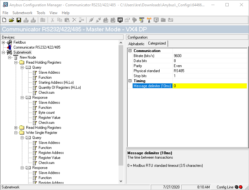
This is usually an issue with the message delimiter. Try some other values, like 100 or 50 for example, and see if the values show up in the node monitor.

Kyle

At your suggestion, I tried increasing the message delimiter value. 50 is the highest that the software will allow. In any case, I still see no data values in the Node Monitor, but there are definitely numbers in the log file.

The node monitor looks like this:

Config file and log file attache.

Still scratching my head…

Ross

Config4Kyle.cfg (16 KB)

Config4Kyle.cfx (14.1 KB)

log-7272020.txt (4.22 KB)

How many registers are you trying to read? You 14 in the query and 17 in the response.

Also, the values in the log are just what the communicator is sending. It’s not receiving a response.

Actually there were 26 in the response. Here I fixed it. Can you try this?

Config4Kyle2.cfg (16.0 KB)

Aside from wiping out the module IP address every time I load it, the config you provided gives me these results:

image.png

Can you set up a Teamviewer so I can log in and take a look?

I am attempting to read 14 registers that make up (I am told) seven 32-bit values. The ‘simulator’ settings indicate ‘High byte first’ and ‘high word first’ are necessary, but the terminaology seems to vary among vendors, so I am not clear is a ‘bite’ is 8 bits or 16, and if a ‘word’ is 8 bits or 16’.

The log has me very confused, as those values appear in a column marked ‘RX’. I would expect those to be received from the end node.

A byte is 8 bits and a word is 16 bits. It sounds like you are trying to read DWORDs, so it would be 28 bytes total.