
I am not clear on how to read the data on the Ethernet/IP network. My desire would be to simply read the global tag. But, it’s not clear that any tags are created when setting up the transactions for the modbus clients.
Hello,
The AB9006 is set for an Ethernet IP Scanner to connect to the AB9006 to read Modbus Data from a Modbus Slave end device. The Ethernet IP Interface on the AB9006 is an Ethernet IP adapter. It will not generate any tags, as the only configuration is that is done is the networking to connect the Adapter interface to the Scanner.
Are you looking to have a Modbus Master device pull data from an Ethernet IP server device?
So, I guess I will lay out the data flow. I have a modbus TCP/IP device which is the Modbus card on a Siemens PLC. The modbus registers on the PLC will be set up as “transactions”. I have a Delta V controller that will be using Ethernet/IP protocol to communicate. So, i need to know how the AB9006 exposes or makes those modbus registers available on the Ethernet/IP network.
The Modbus Client will pull data from the Modbus Server. The data is then placed to the Input/Output area of the Communicator (Dependent upon the type of transaction). The data from the Modbus IO Area is then transferred to the Ethernet IP IO area.
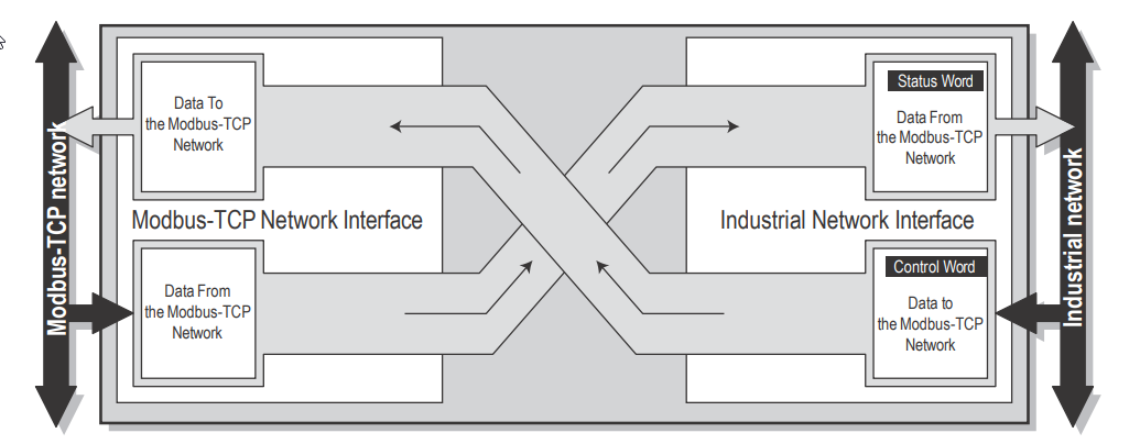
The Ethernet IP Scanner will then pull the IO data from the Ethernet IP Interface of the communicator.
6.5.3 Mapping Overview
This page provides a description of all data resulting from the transactions of the currently applied configuration. It is divided into two parts. The first part describes the X-gateway interface to the EtherNet/
IP network, and the second part all applied transactions on the Modbus-TCP network.
If needed, it is possible to print the configuration to paper. Click the printer symbol to the right on the
mapping overview page to access a printer friendly version of the mapping overview.
EtherNet/IP
The I/O mapped data will always be presented according to the following priority order:
• Input data
Data from the Modbus-TCP network to the EtherNet/IP network.
- Status word (optional)
- Live list (optional)
- Input data (bit transactions will always be mapped first)
• Output data
Data from the EtherNet/IP network to the Modbus-TCP network.
- Control word (optional)
- Output data (bit transactions will always be mapped first)
The parameter section data presents a detailed list of all data, including both the I/O mapped and the
not I/O mapped data, available acyclically from the X-gateway to the EtherNet/IP network. This list
also includes the transaction status and exception code lists, available for error identification. - “Exception Code List” on page 16
- “Transaction Status List” on page 15
Modbus-TCP network
A detailed list of all Modbus servers and transactions in the configuration.
There is an example of the Mapping overview in the User Manual of 6.5.4.
If you need more information on Modbus, I highly suggest Simply Modbus. A great resource to explain the Modbus Protocol.
The modbus protocol is not the issue. I’m well versed there. It’s the Ethernet/IP side of things. So, since i have my DCS device setup, I will ask more directly. I also did not see the modbus map showing the instances and such, which is starting to refresh my memory of CIP. Dealt mostly with DeviceNet in the past. Anyways…
When i set up my logical device in my DCS (DeltaV). I have the option of using 4 messaging Classes: Class 1 Implicit, Class 3 Explicit, Class 3 with PCCC, UCMM with Logix Tags.
So, it seems we are limited Class 1 or Class 3. Now, looking at the overview on page 40 I want to relate this info to my DCS configuration. My options when selecting Class 1 Implicit are as follows:
Input size in bytes:
Output size in bytes:
Input Assembly Instance:
Output Assembly Instance:
Configuration Assembly Instance:
I believe that this is referring to the Control and Status word? So instance 256 and 257? Not sure what the Configuration instance is. But, how do i read the data in New_trans1.
What seems more transparent to me is the option of Class 3 Explicit. My options here are:
Class ID:162
InstanceID:266
Then each signal has a byte offset which I would define of course based on the correlated modbus register depending on size. Also asks for Attribute ID:5.
Do i seem to be on track?