Air Compressor Anybus Config

Good afternoon,

I spoke with Kyle a little while ago and he requested that I send him a copy of the configurations as well as a few seconds of the logging from the anybus AB7007-C module. I have attached these items. Please let me know if anything else is needed or what the next step would be.

Thank you,

Thanks Charles,

Is there any way you can send me the actual .cfg file that you get from saving the project to disk?

Kyle

Charles,

A couple things I’ve noticed from the configs:

You have the fieldbus set to Modbus RTU when it should be set to EthernetIP & Modbus TCP. This will definitely cause issues.

The log shows that you are sending but not receiving anything back. I’d like to see the actual .cfg file to confirm this, but it looks like you are using 6 digits for the register addresses on your slave, like 400001, 400002, etc., when the first digits are actually the command. Can you try it after dropping the first 2 digits so it looks like this 0x0001, 0x0002, etc.?

I did try calling but it went to your voicemail.

Kyle
603-893-5636

Hi Kyle,

Sorry about that. I was looking into another issue for a bit there. I have attached the config file for you to review. I’m unaware of why the fieldbus states Modbus rtu, I do have the config set for Ethernet IP & Modbus TCP and the register addresses are set to the 0x0001 form. It’s possible that I have not done something correctly when loading the config on the new anybus, this is my first time working with one.

Thanks,

Hi Charles,

The file that I really need is the CFG file not the CFX file. Can you send me that one?

Thanks,

Kyle

Hi Kyle,

I’m unsure of how to retrieve the CFG file. When I save the config it comes out as a CFX.

Thank you,

When you save the config in Anybus Config Mgr it should download two files:

image

Hi Kyle,

Sorry about that. Please see the attached config file.

Thank you,

This config file looks pretty good. No errors jump out at me. Have you made sure it’s been successfully downloaded to the device?

Make sure you are connected via the DB9 to RJ11 adapter (you may need to use a USB-to-serial adapter if your PC doesn’t have a serial port). Go to Tools > Port and select the correct COM port.

Click Connect:

image

Then click Download:

image

You should see a progress bar:

image

If it finishes with no errors, than the cfg file has been downloaded.

Is this how you have been doing it?

Kyle

Good morning Kyle,

Yes, this is how I’ve been downloading the config file. We do use a USB to serial adapter and I have verified the correct com port and the download works without issue. The config you have is the one I uploaded from the anybus controller. We also tried reversing the polarity of the RS-485 line to the anybus thinking that maybe the signals are switched. That also did not work.

Thank you,

From the logs before, it looks like you are transmitting but not receiving and the config file looks good. This leads me to believe that there is a problem with the cabling or the serial device itself. How is this wired? Are all of these nodes daisy chained?

I don’t remember if we already went over this or not, but did you check the pinouts and make sure there are resistors as shown here in the manual?

There seems to be some way that they are daisy chained, in a test yesterday I changed the Modbus address of the second air compressor to 1 and it caused a communication failure from the first air compressor. I also tried to just modify the config for air compressor 1’s anybus to handle both air compressor 1 and air compressor 2, however it caused the anybus module to fault. So I restored it to only handle air compressor 1. I would have to forward your request to review the pinouts and resistors to their onsite e tech. Hopefully he can get back to me soon about this.

Thanks,

OK. Please have the onsite tech review the wiring / pin out info in that document.

I am seeing 11 nodes (1 - 11) in the cfg file, which I assume are all separate air compressors. When you say

This makes it sound like there are more than one anybus. I thought all the compressors were connected to the same one. Does each compressor have it’s own anybus?

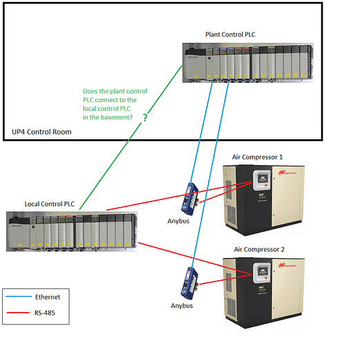
Do you have a diagram of the setup by any chance?

There are only 2 air compressors and each compressor has it’s own anybus module. I have what I believe to be a wiring layout. I’ll see if we can supply that for you.

Thank you,

Charles Dahill

Hi Charles,

Kyle is on vacation today but I am keeping an eye on this issues. Reviewing this case it looks like configuration is setup to connect to one node at Node/slave ID 2. As kyle pointed out from the logs it looks like it is sending 10 messages out but not getting a response to any of them.

This type of issue is typically associated with an issue on bottom three layers of the communication protocol. The wiring, the serial configuration or the messaged particularly the node id for modbus.

I would recommend you start by making sure the Wiring is correct if it is you will then want to make sure the Serial settings the communicator is using matches the settings on compressors and the Node id being used matches.

Deryck

Hi Deryck,

Thank you for the response. I am having the Corix site tech review the wiring to make sure everything is correct from that end. I will let you know what their response is when I get one from them.

Thank you,

Hi,

Thanks for following up, I will keep an eye out for further updated.

Regards,
Deryck

Good morning Deryck,

We have gotten a response from Corix on the pinout and a basic wiring diagram. Here is the response from Corix in regards to the RS485 connector:

“We just checked the pins for the RS485 connection and found them to be incorrect. The RS485 + and – were on pins 6 and 7. We have made the correction and moved the RS485 + and – to pins 8 and 9. We connected everything back up and checked the Wonderware control screen; however, we still did not see any feedback from the compressor. The anybus has more led lights illuminated than before.”

I made a crude diagram that depicted what I believe the wiring for the air compressors looked like (in terms of what PLCs are connected and how) and asked them if it was correct. Here is the diagram.

Here is their response to the diagram:

“The drawing is correct; however, the green line with ? can be updated to ControlNet.”

Thank you,

Charles Dahill

Hi Charles,

Thank you for the diagram. They said the Anybus has more LEDs illuminated than before? Can you tell me the status of those LEDs? (color and blink pattern)

image

Can you also go online and take a quick log and send it to me?

Thank you,

Kyle