Hello,
I have a problem with my Anybus CompactCom M40 ModbusTCP. The SPI communication between host and module get stuck at ABP_ANB_STATE_SETUP. Becaus of that I need some help to fix this problem.
-
Environmental conditions:
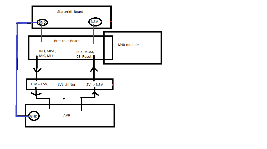
I have connected a Anybus CompactCom M40 ModbusTCP module with the starterkit to a microcontroller of microchip (ATmega2560). The preferred communication between the host and the module should be SPI. I have adapted the generic-examplecode from the HMS-website in compliance with the HMSI-27-334.pdf (Host Application Implementation Guide) but I am stuck at the end of Step 1 in the Guide. My module seems to get stuck at ABP_ANB_STATE_SETUP (right LED on the module shines green. Left LED on the module is off). But I have made some debugging and measurements to make it maybe more possible and easier for you to help me. -
Send data from the host:
I have printed out every byte of data before I store it into the send-register of the controller. What I can see and what I have verified is that the host tries to send the same data every call of the driver. I have read the hms-hmsi-216-125.pdf (Software Design guide chapter SPI) and analyzed the send data. Every byte seems to be what it has to be.
The send data is the following (in hex):
0x85 0x00 0x08 0x00 0x00 0x00 0x00 0x00 0x00 0x00 0x00 0x00 0x00 0x00 0x00 0x00 0x00 0x00 0x00 0x00 0x00 0x00 0x00 0x00 0x6A 0x77 0x3E 0x1C 0x00 0x00
- receive data from the module:
I have also printed out the received data from the module, but this data is different at the most time
The received data from the CompactCom-Module for example is the following:
0x00 0x00 0x00 0x00 0x00 0x00 0x00 0x00 0x33 0x01 0x06 0xB8 0x11 0x8E 0x0E 0x71 0xB6 0x71 0xB6 0x71 0xB6 0x71 0xB6 0x71 0xA9 0xC0 0x00 0x00 0x00 0x18
Further more I have read in the Software Design Guide that it is normal that the host tries to send every call the same data until he get a good CRC.
-
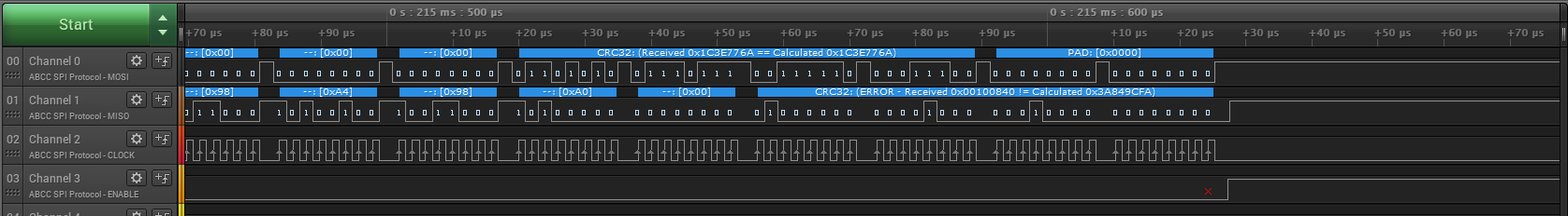
CRC-Function
After I have read some posts in this forum I tried to analyze the CRC32-Function of the driver and I have tested this function with the examples in Appendix H. For my surprise the calculated crc does NOT match with the crc of the example. So I changed the code of the function to the example code given in appendix H. After that, the function calculated the correct crc for every example. But for my surprise, this did not changed anything. The behavior of the driver using SPI as described at the beginning of this post is still the same. -
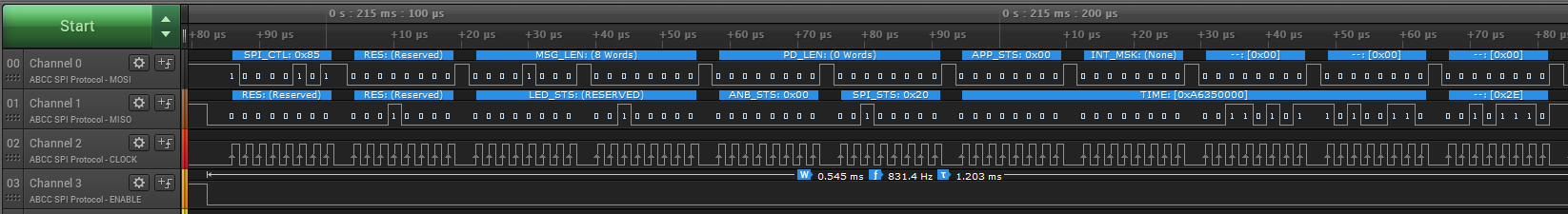
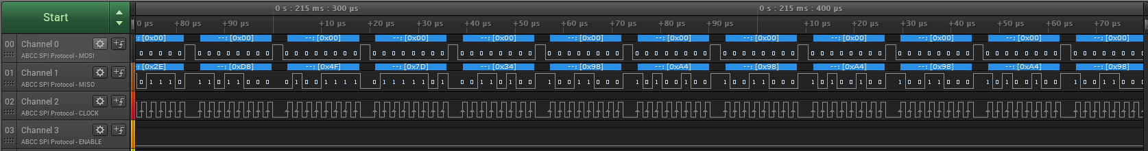
physical send and receive data
After that I have analyzed the send and received data with a logic analyzer. The data on the MOSI and MISO-wires are still the same as described. I have also verified with a oscilloscop, that the voltage-levels of the data is good enough. Nevertheless I have stepped down the speed of the spi transaction in little steps from 8MHz down to 0,5MHz Clock-Speed. But this did not changed anything either. -
configuration of the driver
After I still spend to much time to make it run, I tried to change the communication channel from SPI to serial. This worked at the first try. The module starts as expected and can communicate over the ethernet-network. So I thought that the driver should be configured correctly, because I only changed the communication channel. I have noticed that the driver uses a crc16-function for serial communication. This function works as expected and described in appendix G of the software design guide. I have tested it with the examples given in there. But as I said, I have tried out the two algorithms for the Crc32 function and this did not changed anything.
Further more I have recognized that the serial communication is described as not recommended for the M40 modules in the documentation. I wonder why it is not recommended.
-
SPI-Configuration
After I have read some more posts in this forum, I have tried out the 4 possible SPI configurations for the host controller (CPOL and CPHA (Clock polarity and Clock phase)). But this did not changed anything either. -
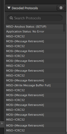
printouts from the debug functionality of the driver.
For the sake of completeness I have also used the printouts from the driver itself. I think that this does not seem to be very helpful but I do not want to hide them. I have enabled ABCC_CFG_ERR_REPORTING_ENABLED, ABCC_CFG_DEBUG_MESSAGING and ABCC_CFG_DEBUG_CMD_SEQ_ENABLED:
Mem: Buffer allocated: 0x00000fe2
CmdSeq(6c6)->00
Command queued: MsgBuf:0x00000fe2 SrcId:0x00
CmdQ status: 1(2)
Outstanding commands: 1
ANB_STATUS: ABP_ANB_STATE_SETUP
ABCC watchdog timeout
I have added every information I have until yet to maybe short the process of support on this topic. But the result of that was that this post is very long. I apologize for my maybe spooky englisch, because it is not my mother language.
I hope someone of you can help me to solve this problem. I am also interested why the vanilla crc32 function of the generic driver does not calculate the same crcs as described in the documentation. Further more I am interested why the serial communication is not recommended for the M40 modules.
Best Regards
zorakon