
The software provided with anybus X-gateway is just great, I can scan and download current configuration of connected device. Problem raises when I try to upload my own project to the device, I cannot fined that Upload button. I even imagine that I should pay some extra for the secret Upload button. Well, can you provide with the one?
Which X-Gateway do you have and which software are you using?
My possession is Anubus X-gateway PROFIBUS DP Master-ModBus-RTU Slave
Article# AB7808-F Serial: A055FFFC
software is Anybus NetTool for PROFIBUS 1.9.1.4
My possession is Anubus X-gateway PROFIBUS DP Master-ModBus-RTU Slave
Article# AB7808-F Serial: A055FFFC
software is Anybus NetTool for PROFIBUS 1.9.1.4
NetTool for Profibus does not have an upload button. You can only download the configuration to the gateway. There is no way to upload the configuration from the device unfortunately, so it’s important to always save a copy of the configuration.
Make things clear please, you mean when I press Download button my project must be downloaded to device, right?
Download means download project to the device.
Upload means upload project from device.
It’s the same concept as most PLC software.
Yes it is my bad, I addresses not knowing exactly what I do. Having my project picture on your hands can you choose module addresses for me? Or give me, please, a good reference on addresses 8 bytes DO Total consistency, 8 bytes SO Consistency and so on, what they mean and how to choose from them?
I don’t think I understand the question.
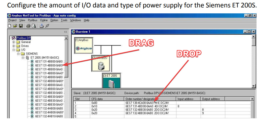
You need to click the + icon to expand the slaves modules:
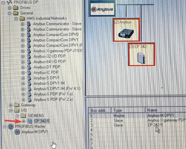
Then you can drag and drop them into the slots (click on slave node).
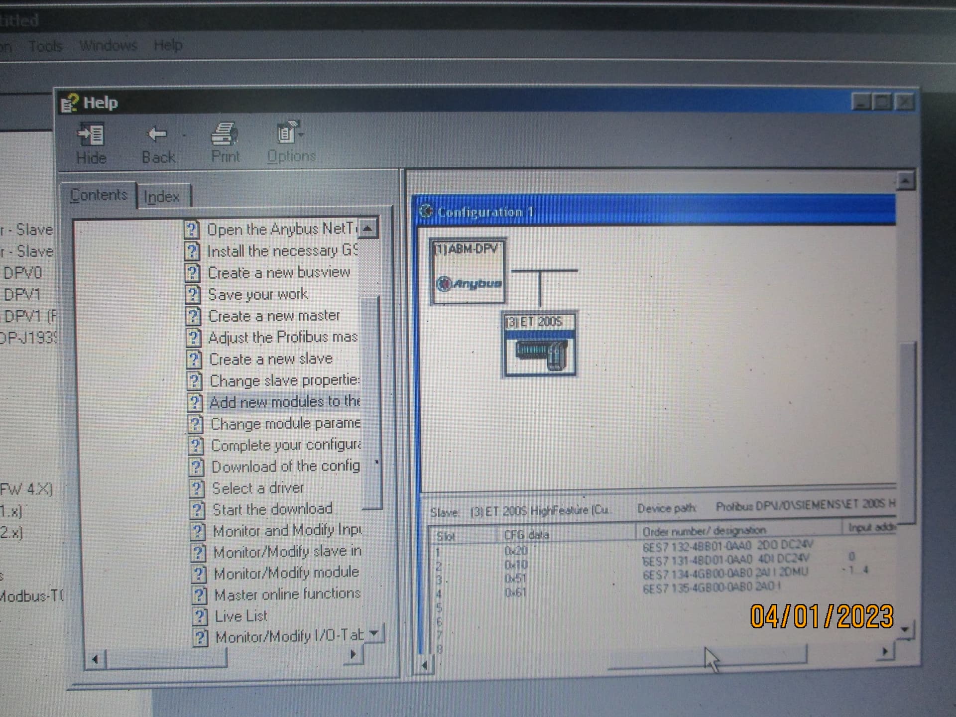
Go to ‘Help > Content…’ and there is a manual which shows you how to use the software.
Right, I was not clear.
A wire connection (old X-gateway connected)
SIMATIC S7-300 → CP342-5 V5.7 → [PROFIBUS Master-ModBus - RTU Slave] → LAN
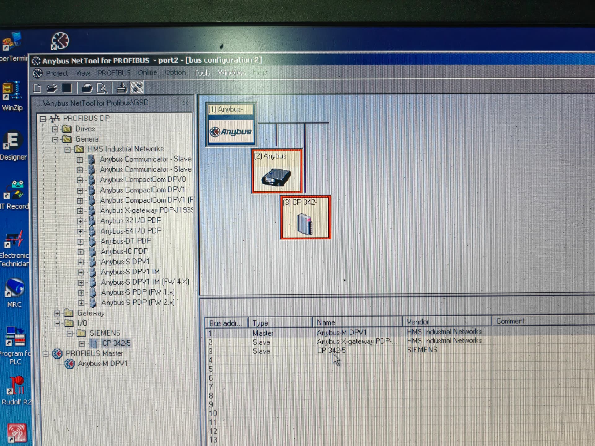
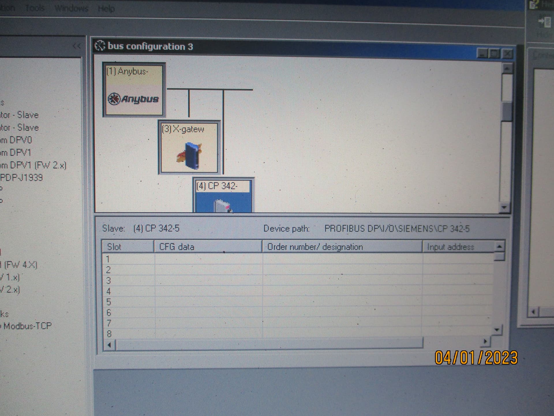
I start my project, on Anybus NetTool for PROFIBUS 1.9.1.4,
Master PROFIBUS → X-gateway → CP342-5
See the image above.
Go to ‘Help > Content…’ and there is a manual which shows you how to use the software.
As software Help says Input-Output addresses are automatically assigned to each module, nothing of that happens on my site, why?.
What do I do wrong?
You need to expand the node using the + icon, then you will see the modules which you can drag and drop to the slots:
This is explained in the manual.
However, I wonder why you are using a Profibus Master to communicate with an S7 PLC? Normally, one would use an Anybus Profibus Slave and configure the Profibus network using Siemens STEP7 (or TIA Portal) when using a Siemens PLC. Are you sure you are using the correct device?
What kind of device are you connecting to on the Modbus RTU side? Is it a Master or Slave?
Software Help says Input-Output addresses are automatically assigned to each module
In my case there is no any Input-Output addresses are assigned, why?
This is explained in the manual.
It is not explained in the manual.
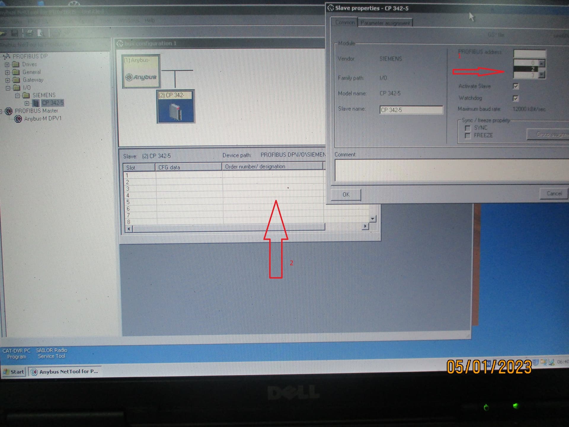
I read Chapter 4 and I understand that when I choose an address, arrow 1 and press OK button, fields, arrow 2, will be automatically filled up for me, right? Why the fields are empty? I reinstalled software.
What is ABC config tool?
This is just another name for NetTool.
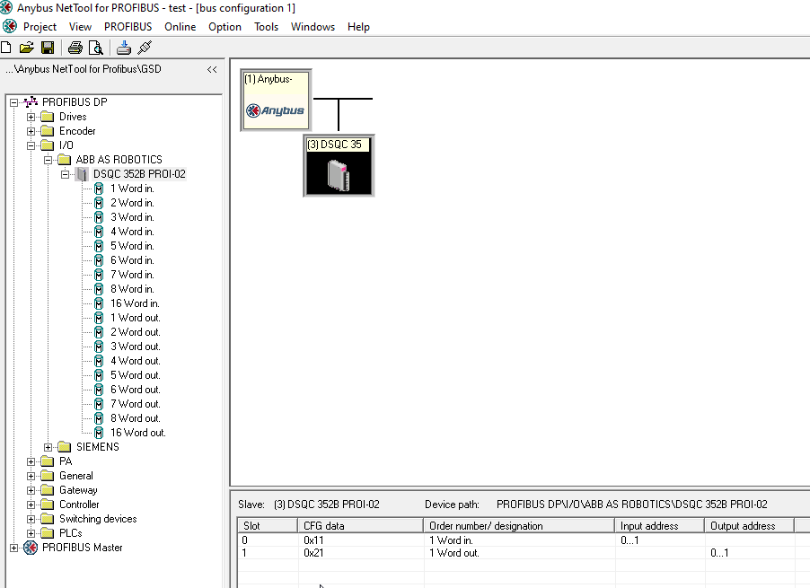
You are misunderstanding. It does not automatically fill up the Slots (IO). You need to drag and drop the IO modules into the slots:
Good.
You need to drag and drop the IO modules into the slots:
How do I choose which IO module to drag?
You choose whichever data you want to receive. Please consult documentation from the Profibus slave to determine this.
documentation from the Profibus slave
Configuration switches.
Node ID invalid, baud rate 9600bps, parity none, stop bits 2.
I have other LAN with Anybus X-gateway and it is sound with the same configuration switches.
CP 342-5
Size of the DP data areas (per DP slave):
– DP input area 244 bytes maximum
– DP output area 244 bytes maximum
Having, what I have on my hands, how do I have to choose which IO module to drag?
If you want to send me the GSD file and the CP 342-5 manual I can have a look, but you should probably ask the manufacturer of the device for the best information.
I download GSD file, it is OK. I give CP 342-5 details from manual as well if you have different manual I would like to see. But whatever I find in the manual question of choosing IO module will come up and I will be here again. Let’s figure a method of choosing IO module out. I am not alone on this one.