MNS EN2MB-R is stuck in "Program Mode"?

I have used the EN2MB-R before, but I’m not an expert.

I am trying to read values from a Rosemount 370XA Gas Chromatograph (Modbus) into an Allen-Bradley PLC (Studio5000-EIP). I am getting a timeout (flashing red LED on MTCP) even though it looks like everything is set up properly.

The only thing I notice that is different than my last time is that when I view the properties of the EN2MB in my Studio5000 program, it tells me that the EN2MB is in “Program Mode”, where the system that runs is in “Run Mode”. I am wondering if that is a symptom or a cause. I can’t find a way to tell the EN2MB to go into “Run Mode”

Thoughts?

Hi Mitchell,

Have you downloaded to both the Anybus and the PLC?

Are you using the Control/Status word?

See page 14 in the User Manual for details on it.

That’s a curiosity. I don’t seem to have any output registers or control registers in my PLC program. The EN2MB-R didn’t create those. As you can see below, the HMS was used to create the software declarations in my Logix 5000 code, but it did not create a control word (EN2MB:C) or an output word (EN2MB:O). It only created the two structures for the two different chromatographs I hope to talk to.

GC_002 is an ABB NGC8203, which is the exact same unit as I talked to in a previous job (and which works fine). GC_003 is the Rosemount which I have not talked to yet. GC_002 is without power at this time and the Transaction Monitor says that there is no connection. However, the Transaction Monitor for GC_003 reports a Timeout.

You have to enable the Control/Status words if you want to use them.

I guess I don’t understand the previous question that well. The Anybus doesn’t really have a “program mode” but the PLC does.

If the transaction monitor is reporting a timeout, it means it’s not getting a response from the server. Can you use a Modbus simulator to poll it?

  1. Where do I find the setting to enable the control words? They don’t seem to be in the PLC setup.
  2. I verified that I could talk to the 370XA using Emerson’r own MOD2020 software package. It has a “Modbus Test” function. I put in a register and a Code 3 to read registers and saw valid values come back. But that was from my laptop directly to the device. It was not through my PLC.

I wonder if I have an AOP file which is not current? Both EN2MB devices on our projects are revision 1.006.

With regards to “Program Mode” and “Run Mode”, I’m not referring to the PLC’s program. If I go online with my running PLC program, I can look at the properties of the EN2MB. It tells me if the device is online (physically connected) and able to talk to the PLC. It also gives me its revision number, whether the device is “owned” by the PLC and what the status of the device is. In my case, the EN2MB is reporting to the PLC (according to the AOP) that it is in Program Mode, not in Run Mode. I’ll be happy to send an image once I arrive back at the site and can get online with the system.

If you can poll the server using a Modbus simulator, you should be able to use the same command and register address to poll it with the Anybus.
The Anybus Client and the Emerson Server are both in the same subnet? Are they connected through a switch? Can you connect a laptop to the second Anybus Modbus port on the bottom (or the switch) and ping both?

What version of RSLogix 5000 do you have? The AOP should be included, but you can re-install it. There are instructions here:

Add On Profile Crashing Studio 5000 Logix Desgner - Anybus Support / Anybus Gateways - hms.how (hms-networks.com)

Yes, this would be helpful, thank you.

OK… here is the original issue…

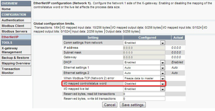
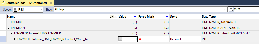
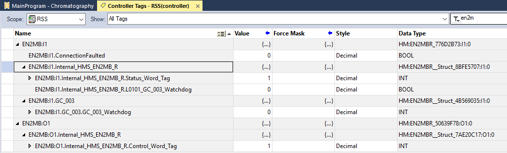
I found the Control Word setting in the EN2MB dialog box was Disabled, so I enabled it and downloaded the new configuration from the EN2MB to the PLC and downloaded that new program change into the PLC. I went into the PLC and changed the control word from a zero to a one.

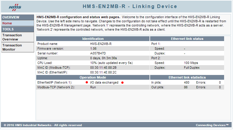
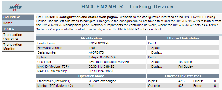
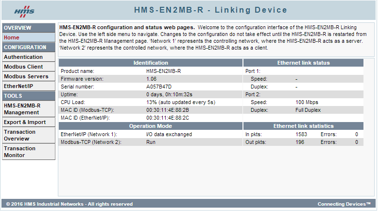
Looking at the HMS, it now appeared that the PLC was communicating with the EN2MB, as the message used to report that Data was NOT being exchanged.

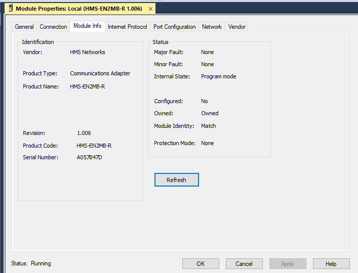
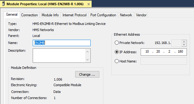
Checking the EN2B Properties Panel is Studio 5000 new showed me that the EN2B was in Run Mode.
image

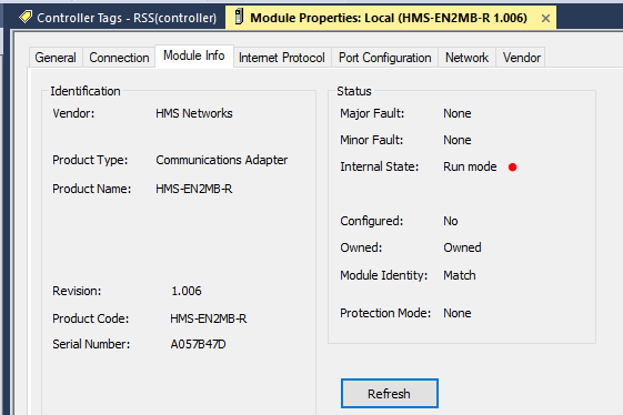
So that answers my original question and gets me closer… BUT I still get no data transfer.
We should probably consider this a second issue to solve.

ISSUE 2:
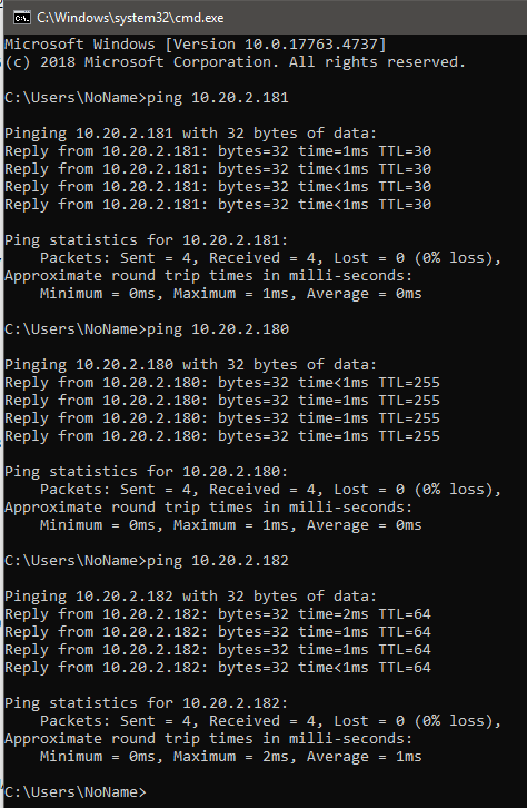
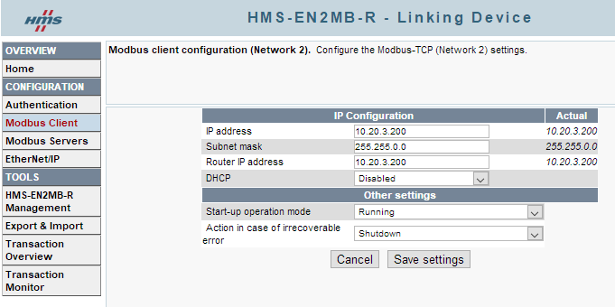
I have power applied and it has booted up. I can ping the EN2MB from the LAN:
image

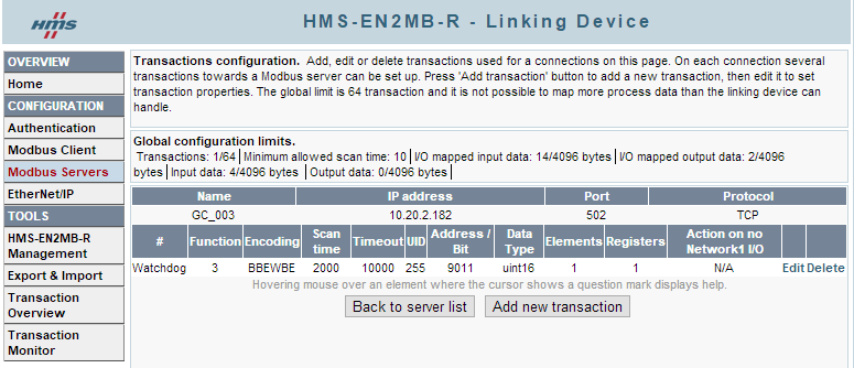
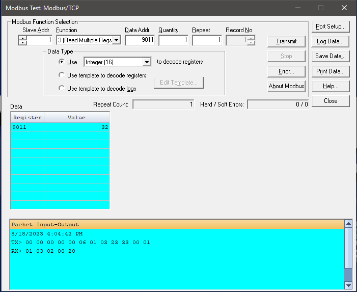
However, the Transaction Monitor is still insistent that there is a “Timeout”. After the timeout, all subsequent transactions describe the Linking Device as having disconnected.
image

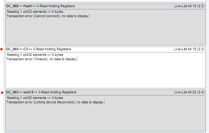
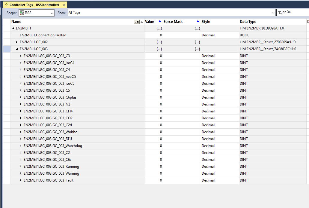
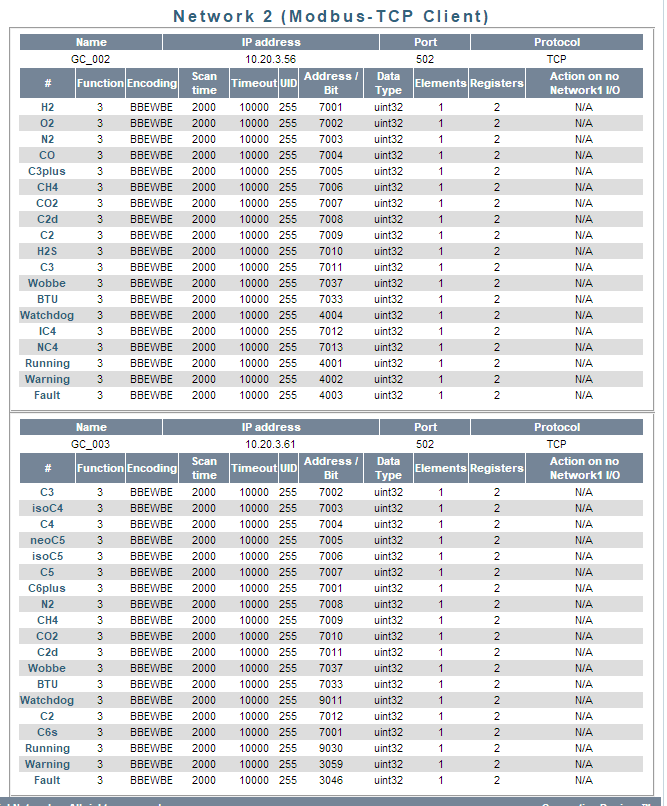
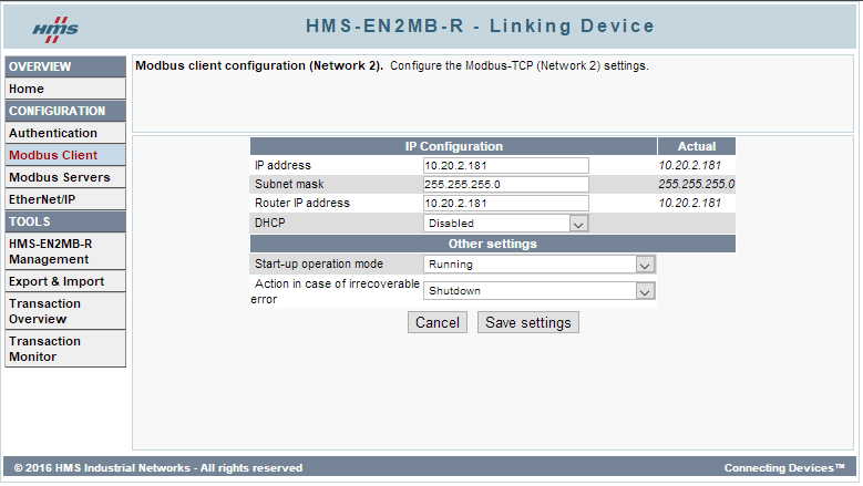
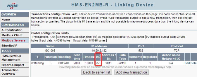
I don’t know if this means that the PLC is not able to read from the EN2MB or if the EN2MB is not able to read from the 370XA. In my Modbus Configuration, I have two devices. GC_002 has now power or wiring to it yet, so there’s no surprise that I cannot connect to it. However, GC_003 (the 370XA) has power, and is able to be pinged on its own subnet as 10.20.3.61.

Perhaps I have the EN2MB set up incorrectly as far as being able to cross over the two distinct subnets of 10.20.2.xxx and 10.20.3.xxx, but I think I have it set up the same as the system that works.


image

Let me know what else I could show you that might lead me to a solution.
Thanks! (looks like progress to me so far!)

Hi Mitchell,

This means the Anybus cannot reach the 370XA.

It sounds like a routing issue. If the Modbus client is in the network 10.20.x.x with mask 255.255.0.0, the servers also have to be in the network 10.20.x.x with a mask of 255.255.0.0.

Did you try pinging the 370XA with a laptop connected to the second Modbus port on the Anybus and an IP in the same subnet, like 10.20.3.201 255.255.0.0.

To remove all doubt about crossing subnets, I have moved the chromatograph into the same subnet.
10.20.2.180 = EN2MB - EtherNet/IP
10.20.2.181 = EN2MB - MODbus TCP
10.20.2.182 = EN2MB - 370XA Gas Chromatograph

The variable I am reading is the current time in seconds. I am still getting Timeout messages:

PLC is configured to talk to the EIP ports on the front of the EN2MB:
image

Both sides (EIP and Modbus) seem to be working properly:

\

Setup of the Client seems correct.
Please verify that it is allowable to have “IP Address” the same as “Router IP Address”.

As is my single transaction… to make it as simple as I can:

HOWEVER… when I use Emerson’s MOD2020 software to talk directly to the 370XA on the exact same network, I see this:

Color me confused…

I think I see the problem:

image

Try changing that Unit ID to 1.


mitchell.hein

I have already tried that and it did not make a difference.
After reading the help notes, that UID is only for Modbus RTU, and I am using Modbus TCP.

The string of data that constituted a valid data request can be seen on my previous post:
TX> 00 00 00 00 00 06 01 03 23 33 00 01
image
…there is normally a lead-in of 3.5 bytes or more of blanks [00]. I’m not sure what the [06] is.
The [01] is the slave address, the [01] is the UID, the [0323] is the address to be read which translates hex to dec as 9011 (correct register), and the [0001] must then be the CRC checksum.

That resulted in a response by the 370XA of:
RX> 01 03 02 00 20
image
… so, [01] is the UID (slave address), [03] is the function, [02] is the byte count, and my data is [0020] which translates hex to dec as 32 seconds into the minute which was correct.

Do you have a way to view the actual transmit command on an EN2MB-R?
Then I could compare the two request strings and perhaps that would show me where it is going wrong.

That’s actually incorrect. The Unit ID is only used for Modbus TCP only. It’s rarely used (they usually will default to 1 or reply on all UIDs, but it’s for when there are multiple Modbus devices that share an IP address. If you can show me where you saw that, I’d appreciate it so we can fix it. Since this device doesn’t support Modbus RTU, I’m not sure why it would be in the notes.

It should be the length, part of the Modbus TCP application header, but that doesn’t make sense if it’s only one register. A Modbus TCP packet should look like this:

The device only has the Transaction Monitor. I would recommend using Wireshark to view the entire raw data packet. You could try connecting the second Modbus TCP port, but most likely will have to use an old hub or a switch with a mirrored port to see all the traffic.

A solution has been found.

A technical resource with Emerson/Rosemount had originally told me that either Ethernet Port (1 or 2) could be used for PLC communications, but that was not correct. I needed to be talking to Port 2, not Port 1. We added a second cable and wired it in. That was the first of three issues that were preventing good data transfer.

Once that was corrected, I tried a user ID (slave address) of 1 instead of 255 and that resulted in my receiving Modbus Exceptions for Incorrect address which was the first response I’d seen… so that was a second issue.

After digging a little deeper, I found a third issue where I was off by one address. In order to receive register 7001, I needed to set up the EN2NB to ask for address 7002. I set all parameters up accordingly and started receiving 100% good data.

I owe a big thank you to everyone who contributed to this answer, both online and offline. Hopefully, this thread will help someone else in the future.

1 Like

Great - That’s got to be a relief to have it working!!

The offset issue is quite common in Modbus because we normally talk about memory areas as starting at 0, and registers as starting at 1, so depending on the documentation, to get the correct address you often have to add 1 or subtract 1.

Please let me know if you have any other questions!

Best Regards,
Kyle

Hi Kyle,

I’m still having issues with the EN2MB-R. Different devices, but similar issues.

I have two more devices which I need to talk to. In one case, I’m absolutely sure that the data address is correct. I know the Unit ID is correct. The TCP/IP address is correct. I can ping the device. I get the same old Transaction Error = 2. I’ve worked with the technical support team for the device and the guy is a whiz at Modbus Communications. He can’t explain why it won’t work.

Do you have a list of other things which could cause a Transaction Error = 2? I have tried the three things which worked earlier in the thread but they don’t work. Is it possible that the Unit ID needs to be set up one number higher or lower than the actual slave address… like the Data Address?

I’m beyond clutching at straws. Both of these new devices exhibit the exact same error.

I finally caught a break.

What I found is that some devices expect you to use the full Modbus Address, such as 40001 for a Holding Register and some devices IMPLY that a Holding Register is always 40000, so you simply declare the address as a 1 to imply 40001. This varies from device to device even within the same company.

Once I edited my requested data address to 1 (instead of 40001) it accepted the request, and I got good data.

OK great - I was just actually getting around to taking a look at this. It’s been a busy Monday here. Glad you figured it out Mitchell and sorry for the delay.