
Hello, I’m trying to connect a Schneider PLC (TM241) which has a serial port (Modbus RTU) with a bar code reader (Pepperl & Fuchs) which has a RS485 interface. For achieve this communication I’m using a AB7010-B gateway. However, the LED #5 is steady red ( Transaction error/time out or subnet stopped). The gateway is not seeing the sensor. Could you help me out with this error?
What do you mean it’s not seeing the sensor? Can you confirm that the bar code reader is exporting data (with a terminal)? Do the bar code scanner require a command to be sent or does it use a manual trigger of some kind?
Can you share the .cfg file from the Configuration Manger and the User manual for the bar code scanner?
Hello Kyle,
Thank you for your prompt answer. Attached you will find all documentation related with my configuration. I appreciate if you
can help me with this configuration.
Let me know if everything is ok.
Best regards
Hello Kyle,
Please, attached you will find the user manual for the bar code reader and also you will find the .cfg file
from the Configuration Manager
Regards,
You need to send a request to the scanner:

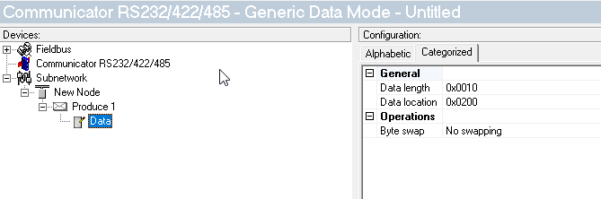
If you change the Protocol Mode to Generic Data Mode and create a Produce transaction with 16 bits, those bits will be mapped to the Output Memory in the Anybus, so you can write to them from your PLC:
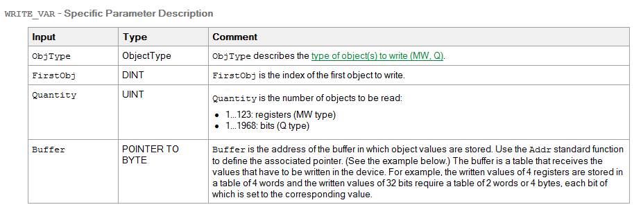
You will have to create a Consume transaction for the scanner’s response (21 bytes):
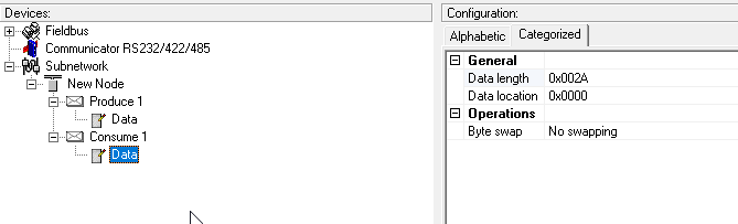
Make sure to set the Input size to 21 bytes and the Output size to 2 bytes in the PLC.
I did what you suggest but I still having the LED#5 Flashing. Please, find attached the .cfg file. Below you will find a capture of the subnetwork status.
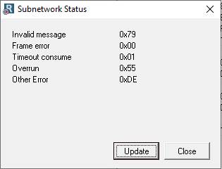
Pressing update button ‘’ Other Error’’ change the value.
Do you know which can be the error?

![]()
Hello Kyle,
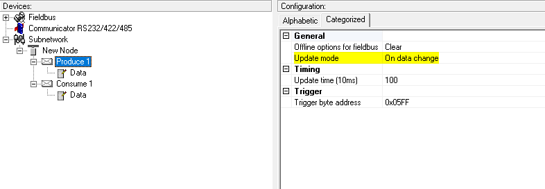
I did the modification that you suggest (on data change) but the LED #5 still on in red. The way that I found to clear the
LED5 was setting on the consume transaction the timing (offline timeout time) to 0. Is this configuration correct?
Attached you will fin a document with the configuration of the gateway and also a document with the communication configuration of the PLC because, I can
read from the gateway with the PLC but I have an error when I try to write into the gateway from the PLC.
Basically, I still without can communicate with the sensor.

![]()
Gateway_Configuration.docx (472 KB)
PLC_Configuration.docx (278 KB)
Hi @MattLass,
As far as LED 5 goes. You can disable the timeout to turn it off, but then it won’t alert you to a timeout. It is possible for the unit to function perfectly fine when LED 5 is lit when there are occasional timeouts, but the data is still being transferred, but this is normally indicative of a problem.
Can you provide your config file for the AB7010 (.cfg) as well as the actual write command you are sending it, including the register address? That should allow us to find the issue. Thanks for your patience.
Kyle
Hello Kyle.
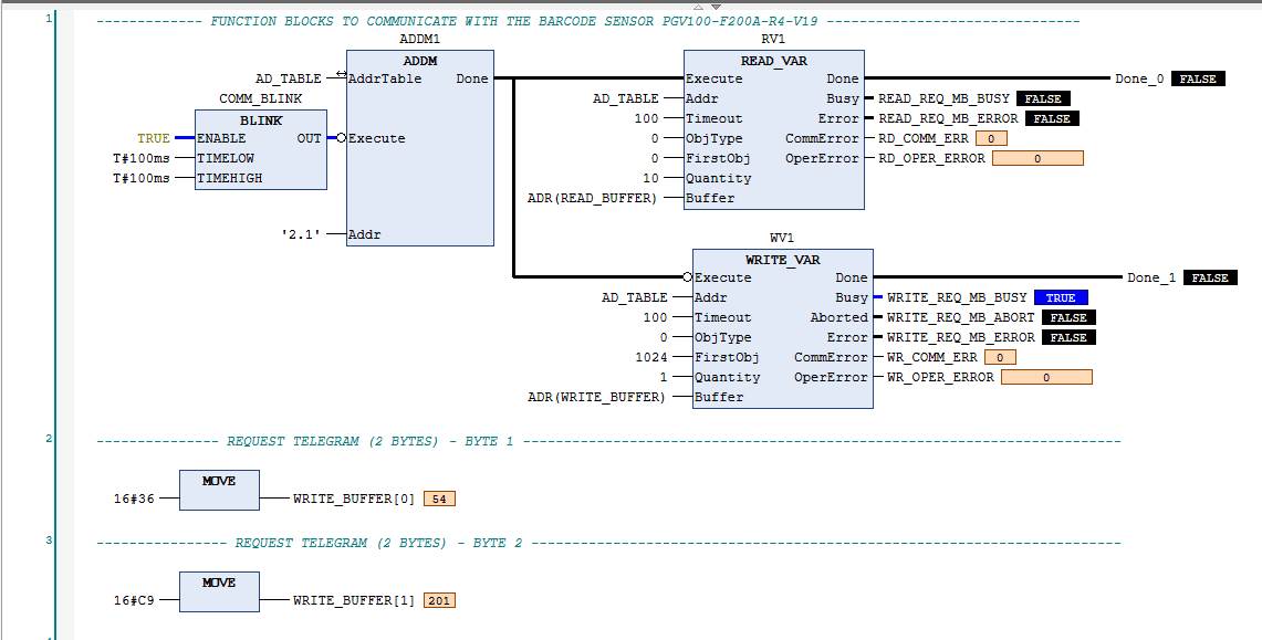
Thank you so much for your support and prompt answer. Please, find attached the AB7010 configuration file. Attached you will
find a capture of the Write block that I’m using to communicate the PLC with the gateway.
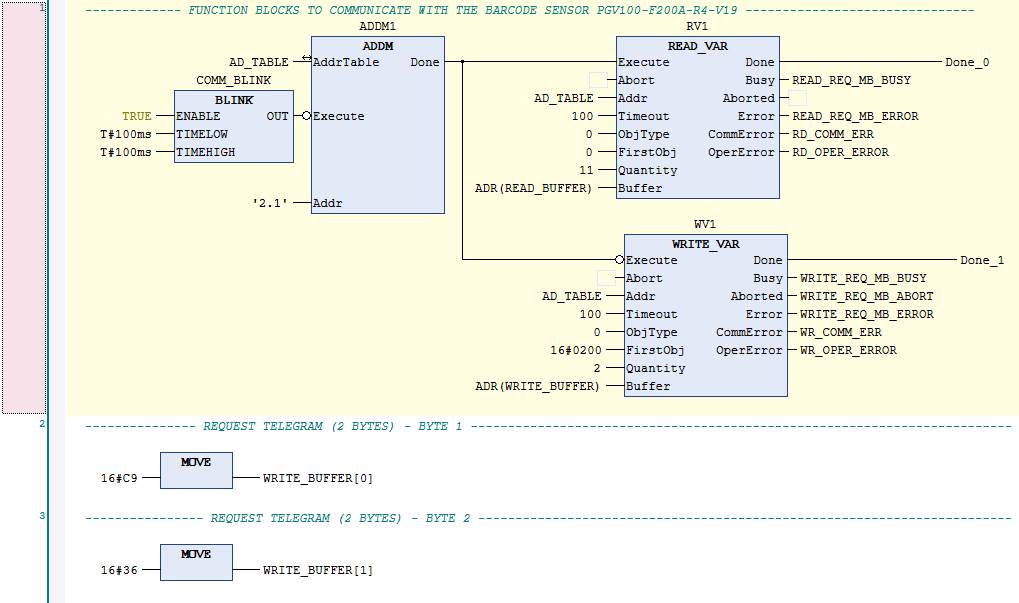
The inputs of the block are:
FirstObj = 16#0200
Quantity = 2
Buffer: WRITE_BUFFER : ARRAY[0…2] OF INT;
Based in the manual of the sensor, the sensor will only send the data when you send a command first. The PGV (Sensor) is at Address 1 then command is two
bytes 0xC9 0x36
Let me know if everything is ok.
Best regards,

![]()
PGV100_20200206.cfg (16 KB)
From what I can see from the screenshots provided, it looks like you are trying to write the correct register, 512 (0x200), the Output area of the gateway, with two bytes:
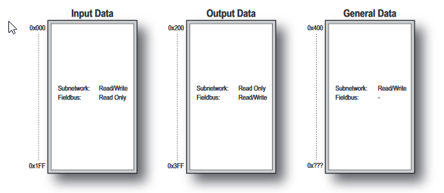
Can you confirm?
Yes, Kyle. I’m trying to write two bytes in the output data area of the gateway

![]()
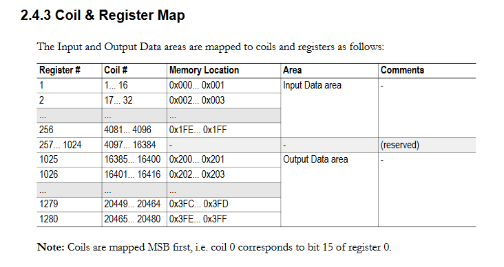
I change the value from 512 to 1025 but Im still having the same error.
Should I change the produce data location too (Actually is 0200).?
Should I change the protocol Mode to Master Mode (Actually Generic data mode) and use transactions?
Regards,
![]()
No.
I don’t think that’s necessary.
Do you need to include in the function code (for example, 41025)?
Can you also just try 1024, 0, and 1?
Would you be available to do a Teamviewer session to troubleshoot this?
Hi Kyle!
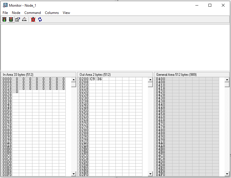
It works! I’m using 1024.
Now, I’m seeing the values in the out area 2.
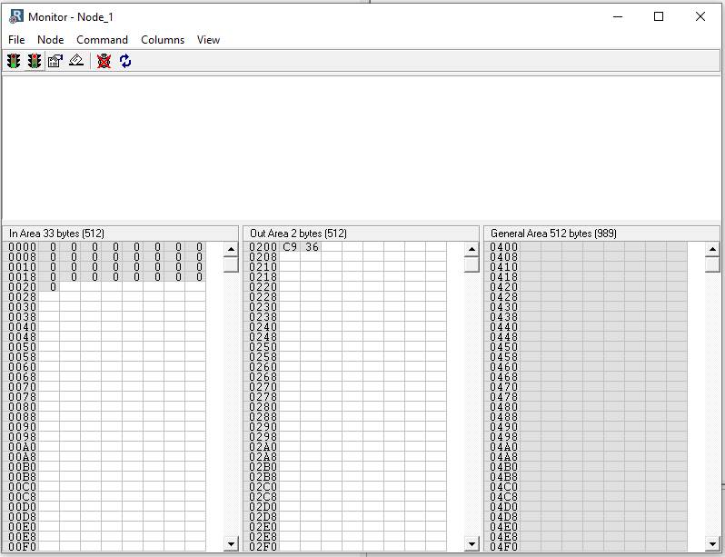
Obviously, if I enable the timeout time I have the time out error (LED 5).
I will check the configuration on my sensor and if you are able we can have the TeamViewer session.
Thank you!!
Regards,
![]()
You may not even want to use the timeout in this configuration as you aren’t doing cyclical transactions.
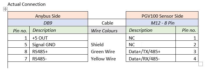
Hi Kyle, I checked the configuration of the sensor and everything seems fine. Now I’m checking the connection between them. Could you revise the attached document and tell me if the connection is ok.
Regards
Matias Lasarte
Programmer - Designer
Hi Kyle,
Based on your RS485 two wires connection of your manual. Is it mandatory the 470 ohm between the +5v pin and the RS485+ pin? Those resistors
are internals?
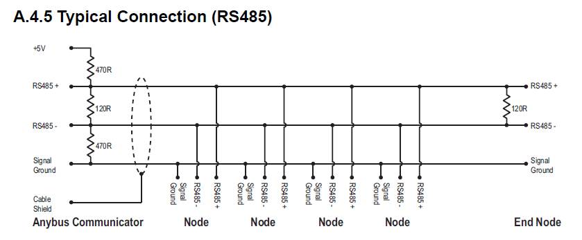
I’m sending the command but there is not answer from the sensor. Is there a way to know from the software if the command have been transmitted?
![]()